background image


Jetter AG 

17 


JXM-MUX 

Electrical installation 

Power Supply Jack POWER 

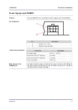
The jack POWER is for connecting the power supply cord to the JXM-MUX. 


8

1


Pin 

Description 

VIn (DC 10 V ... 32 V) 

Reference potential (GND) 


Parameter 

Description 

Operating voltage 

DC 10 V ... DC 32 V 

Input current at DC 12 V (typically) 

2.0 A max. 

Input current at DC 24 V (typically) 

1.0 A max. 

Power consumption 

24 W max. 


An 8-pole connector (male) is included in the scope of delivery of a JXM-MUX. 

The power supply cord with one red and one black core (each 2 m in length) is 

connected to the connector terminals. 


Purpose 

Pin assignment 

Technical specifications 


Male Connector for 

POWER jack 

Summary of Contents for JXM-MUX

Page 1: ...User Manual JXM MUX Video Splitter 60874930 We automate your success...

Page 2: ...ast a revised document will be supplied only if required by law or deemed appropriate by Jetter AG Jetter AG shall not be liable for errors in form or content or for missing updates as well as for dam...

Page 3: ...ne Sales 49 7141 2550 433 Phone Technical Hotline 49 7141 2550 444 Fax Sales 49 7141 2550 484 E mail Sales sales jetter de E mail Technical Hotline hotline jetter de This User Manual is an integral pa...

Page 4: ...ress info jetter de Your feedback will help us produce manuals that are more user friendly as well as address your wishes and requirements This document contains important information on the following...

Page 5: ...UX 14 Physical dimensions 15 2 2 Ports and interfaces 16 Power Supply Jack POWER 17 Camera Inputs CA1 to CA4 18 A and V AV IN Connections 19 A and V AV OUT Connections 20 CAN port 21 2 3 Mechanical in...

Page 6: ......

Page 7: ...uctions This chapter informs the user of basic safety instructions It also warns the user of residual dangers if there are any Furthermore it contains information on EMC Topic Page Basic safety instru...

Page 8: ...which to a high degree have to be fail safe The JXM MUX is no safety related part as per Machinery Directive 2006 42 EC This device is not qualified for safety relevant applications and must therefore...

Page 9: ...ting from the use of non original parts and equipment is excluded The device contains electrostatically sensitive components which can be damaged if not handled properly To exclude damages to the devi...

Page 10: ...ed as shown below The jacks CA1 to CA4 are soldered to the JXM MUX housing A CA1 CA2 CA3 CA4 POWER INPUT DC10V 32V AV OUT Control Box AV IN A V V Klappferrit 7427122 Video Out Cam1 Cam2 Sicherungs b g...

Page 11: ...his chapter covers design interfaces and installation of the video splitter JXM MUX To ensure immunity to interference follow the wiring instructions see page 10 Topic Page Design of the device 12 Por...

Page 12: ...rical installation 2 1 Design of the device This chapter describes the design of the device Topic Page Product description 13 Interfaces of video splitter JXM MUX 14 Physical dimensions 15 Introductio...

Page 13: ...implemented CANopen protocol The product features are listed below Video system NTSC PAL 5 channels 4 camera ports 5 pin MiniDIN jacks 1 video input RCA cinch 1 audio input RCA cinch not supported 1...

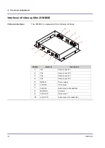
Page 14: ...terfaces 1 2 3 5 6 7 8 9 10 Number Element Description 1 CA1 Camera input 1 2 CA2 Camera input 2 3 CA3 Camera input 3 4 CA4 Camera input 4 5 POWER Power supply 6 V AV IN Video input 7 A AV IN Audio in...

Page 15: ...e physical dimensions of the JXM MUX in millimeters 5 6 6 12 154 130 12 5 10 10 19 19 17 17 69 28 28 105 5 5 A CA1 CA3 CA2 CA4 POWER INPUT DC 10V 32V A V V AV OUT MONITOR AV IN The video splitter JXM...

Page 16: ...nput for a video signal The function of the RCA cinch jacks V AV OUT is as follows Output of a resulting video signal The function of the CAN interface is as follows Configuration and control of the v...

Page 17: ...tion Operating voltage DC 10 V DC 32 V Input current at DC 12 V typically 2 0 A max Input current at DC 24 V typically 1 0 A max Power consumption 24 W max An 8 pole connector male is included in the...

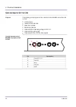
Page 18: ...CA1 to CA4 CCD cameras Internal vehicle cameras Rear view cameras Monitoring cameras Cameras with an operating voltage of DC 12 V Cameras with audio output Cameras with PAL or NTSC video signals 1 2 3...

Page 19: ...video signal via AUX input RCA cinch jacks Audio signals are not supported 1 2 3 4 Pin Description 1 Video input signal V AV IN 2 Reference potential for video signal 3 Audio input signal A AV IN not...

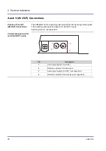
Page 20: ...ing video signal is output via V AV OUT jacks Audio signals are not supported 1 2 3 4 Pin Description 1 Video output signal V AV OUT 2 Reference potential for video signal 3 Audio output signal A AV O...

Page 21: ...able the video splitter JXM MUX is connected as CANopen node to a CANopen bus 1 2 3 4 Pin Description 1 CAN_H 2 CAN_L 3 4 Jumper CAN terminating resistor 120 A 2 core power supply cord 1 m in length i...

Page 22: ...22 Jetter AG 2 Electrical installation 2 3 Mechanical installation This chapter describes how to install the JXM MUX Topic Page JXM MUX Installation 23 Introduction Table of Contents...

Page 23: ...n 1 Install the JXM MUX in a location which has a load carrying capacity of at least 5 kg 2 Screw down the JXM MUX as shown in the illustration below When doing so use the screws that come with the mo...

Page 24: ......

Page 25: ...ter AG 25 JXM MUX Configuration 3 Configuration This chapter describes how to configure the video splitter JXM MUX via CANopen interface Topic Page JXM MUX Configuration 26 Introduction Table of Conte...

Page 26: ...flash memory and is thus safeguarded against power loss To set the NODE ID enter the required value into index 4000 subindex 4 length 1 e g 0x3F To store the newly set NODE ID to index 1010 subindex 1...

Page 27: ...Jetter AG 27 JXM MUX Configuration All available objects are listed in the following illustration For a detailed definition refer to the EDS file Object Directory...

Page 28: ...screen mode index 4000 sub index 5 only valid if not 0 and not 0xFF Bit 0 1 Channel 0 3 for left split screen half default channel 0 Bit 2 3 Channel 0 3 for right split screen half default channel 1 B...

Page 29: ...MUX NodeID_JXM_MUX 0x7F Event time in ms Event_Time 1000 Inhibit time in ms Inhibit_Time 100 End_Const Var Permanent PDO mapping of CAN data to JXM MUX PDO1tx Array 6 of Byte End_Var Task JXM_MUX_Cont...

Page 30: ...MD_NMT_ALLNODES CAN_CMD_NMT CAN_NMT_START End_Task The following program is for selecting 4 channel split screen mode of the JXM MUX module The image of camera 4 is displayed in the top left quarter o...

Page 31: ...4 channel split screen mode PDO1tx 5 0x1B CanOpenAddPDOTx CAN_CONTROLLER_0 CANOPEN_PDO1_TX NodeID_JXM_MUX 0 CANOPEN_BYTE 1 PDO1tx 0 Event_Time Inhibit_Time CANOPEN_ASYNCPDO CANOPEN_NORTR CanOpenAddPD...

Page 32: ...32 Jetter AG Appendix Appendix This appendix contains electrical and mechanical data as well as operating data Topic Page Technical specifications 33 Index 37 Introduction Contents...

Page 33: ...n of the appendix contains information on both electrical and mechanical data as well as operating data of the module JXM MUX Topic Page Technical specifications 34 Physical dimensions 35 Operating pa...

Page 34: ...on 24 W max Parameter Description Video system NTSC PAL standard signal Synchronous system integrated Video inputs 5 channels 4 MiniDIN 1 RCA cinch composite 1 Vp p 75 Ohm Audio inputs 5 channels 4 Mi...

Page 35: ...al dimensions of the JXM MUX in millimeters 5 6 6 12 154 130 12 5 10 10 19 19 17 17 69 28 28 105 5 5 A CA1 CA3 CA2 CA4 POWER INPUT DC 10V 32V A V V AV OUT MONITOR AV IN The video splitter JXM MUX can...

Page 36: ...g temperature range 10 60 C Storage temperature range 25 80 C Parameter Value Standard Vibrations 3 G Degree of protection IP20 DIN EN 60529 Place of Installation Only indoors Mounting orientation Ver...

Page 37: ...WER 17 Jacks AV IN 19 Jacks AV OUT 20 Jacks CA1 to CA4 18 JXM MUX Configuration 26 JXM MUX Installation 23 M Physical dimensions 15 Modifications 8 O Operating parameters Environment and mechanics 36...

Page 38: ...Jetter AG Graeterstrasse 2 71642 Ludwigsburg Germany Phone 49 7141 2550 0 Fax 49 7141 2550 425 info jetter de www jetter de We automate your success...

Reviews: