Page 11
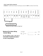
STEP 5: FINAL INSTALLATION STEP
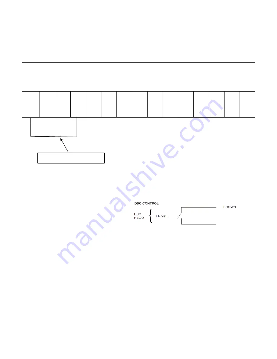
IMPORTANT:
To enable the selected speed control signal, a jumper wire
MUST
be installed, as shown below:
*Optional Fire Alarm Relay
Control Wiring
For installations where a fire alarm
will enable or disable fans please
use this wiring diagram.
Br
o
w
n
Re
d
Gr
e
y
Pi
nk
Bl
a
ck
Wh
it
e
Tu
rq
u
oi
se
Ye
ll
o
w
Gr
e
e
n
Vi
o
le
t
Re
d
/
B
la
ck
Or
a
n
g
e
Bl
ue
Re
d
/
B
lu
e
Gr
e
e
n
/
Re
d
+24
VDC
+10
VDC
Din1
Din2
RSA
(D+)
RSB
(D-)
GND
Ain1
0-
10V
Ain1
4-
20m
A
Ain2
0-
10V
Ain2
4-
20m
A
Aout
GND
Fault
NO
Fault
COM
WARNING: Never apply line voltage to the digital input
Place a jumper wire here
(24VDC)
PINK
(DIN2)


