background image


37                 

DRIVER AND INTERFACE DIRECTLY TO HARDWARE, PROVIDING FAST 
GRAPHIC ACCESS 

IRQ ROUTING :


VIA PCI IRQ MINIPORT DRIVER IS TO BE INSTALLED UNDER WIN98 ONLY, 
IT WILL FIX PCI IRQ ROUTING SEQUENCE 

INF : 


VIA REGISTRY DRIVER IS TO BE INSTALLED UNDER WINDOWS 
THE DRIVER WILL ENABLE VIA POWER MANAGERMENT CONTROLLER 


1.


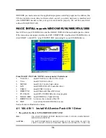
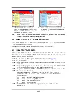
Click IDE when MAGIC INSTALL MENU 
appears 

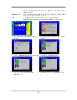
2.


Click NEXT when VIA Service Pack Wizard 
appears 


3.


This is to announce the Copy Write, click Yes 4.


Click NEXT to choose all driver  


5.


Click NEXT to Install ATAPI Vender 
Support Driver 

6.


Click NEXT to choose enabled DMA Mode  

Summary of Contents for 625EMWR1A

Page 1: ...essor NO G03 625EMW Rev 1 0 Release date November 2003 Trademark Specifications and Information contained in this documentation are furnished for information use only and are subject to change at any...

Page 2: ...ADVANCED BIOS FEATURES 22 3 6 ADVANCED CHIPSET FEATURES 25 3 6 1 DRAM TIMING SETTING 26 3 6 2 AGP TIMING SETTINGS 27 3 6 3 PCI TIMING SETTINGS 27 3 7 INTEGRATED PERIPHERALS 27 3 7 1 ONCHIP IDE FUNCTIO...

Page 3: ...BLE FOR ANY INDIRECT SPECIAL INCIDENTIAL OR CONSEQUENTIAL DAMAGES INCLUDING DAMANGES FOR LOSS OF PROFIT LOSS OF BUSINESS LOSS OF USE OF DATA INTERRUPTION OF BUSINESS AND THE LIKE PRODUCTS AND CORPORAT...

Page 4: ...tegrated 3D Graphic Acceleration makes this board lower cost alternative to a video card The motherboard also integrated PCI LAN Controller supports 10 100 BASE T Transfer rate for those whom require...

Page 5: ...mpliant Integrate VGA Integrate 2D 3D graphic Engines 8 16 32 64MB frame buffer using system memory Internal AGP 8x performance Support 24 bit 250MHz RAMDAC TV Out for 625EMWxxx VIA VT1622A TV Encoder...

Page 6: ...Connector VIA VT8623 Chip ATA 100 IDE Connector Front Panel Connector ATX Power Connector CPU FAN VIA VT8235 Chip IR Connector SFAN VIA VT1211 I O Chip Clear CMOS JP5 Speaker Connector Power LED Conne...

Page 7: ...tor 40 pin Block p 13 IDE2 Secondary IDE Connector 40 pin Block p 13 Headers Header Name Description Page COM2 COM2 Serial Port Headers 10 pin Block p 13 TV_OUT for V625EMWxxx S Video RCA Composite TV...

Page 8: ...tio 1 2 3 4 5 6 7 8 9 10 Ratio 1 2 3 4 5 6 7 8 9 10 3 0x OFF ON ON ON ON 10 0x OFF OFF ON ON ON 3 5x OFF ON OFF ON ON 10 5x OFF OFF OFF ON OFF 4 0x ON OFF ON ON ON 11 0x OFF ON ON ON OFF 4 5x ON OFF O...

Page 9: ...fault JP6 2 3 closed USB Power On Enabled JP6 1 3 JP6 1 3 4 CMOS RAM Clear 3 pin JP5 A battery must be used to retain the motherboard configuration in CMOS RAM short 1 2 pins of JP5 to store the CMOS...

Page 10: ...pically used for printers PS 2 a low speed interface used for mouse and keyboards USB Universal Serial Bus a medium speed interface typically used for mouse keyboards scanners and some digital cameras...

Page 11: ...ll see the screen as below then CMOS Setup Utility Copyright C 1984 2003 Award Software Miscellaneous Control Item Help VIA C3 Clock Ratio Default Auto Detect PCI DIMM Clock Enabled Spread Spectrum Di...

Page 12: ...rboard is very easy you can refer to figure 2 4 to see what a 184 Pin DDR200 DDR266 DDR SDRAM module looks like DDR 2 BANK2 BANK3 DDR 1 BANK0 BANK1 NOTE When you install DIMM module fully into the DIM...

Page 13: ...2 5 2 Assigning IRQs For Expansion Card Some expansion cards need an IRQ to operate Generally an IRQ must exclusively assign to one use In a standard design there are 16 IRQs available but most of th...

Page 14: ...itch that connect from the front panel switch to 2 pins Power On jumper pole on the motherboard When the power switch on the back of the ATX power supply turned on the full power will not come into th...

Page 15: ...m to display 8 Audio Connector CN2 Line Out Line IN MIC GAME This Connector are 3 phone Jack for LINE OUT LINE IN MIC Line out Audio output to speaker Line In Audio input to Audio controller MIC Micro...

Page 16: ...the second HDD is referred to as the Slave For performance issues we strongly suggest you don t install a CD ROM or DVD ROM drive on the same IDE channel as a hard disk Otherwise the system performanc...

Page 17: ...Pin1 USB1 USB2 VCC DATA G ND DATA VCC O C DATA G ND DATA 4 IDE Activity LED HD_LED This connector connects to the hard disk activity indicator light on the case 5 Reset switch lead RESET This 2 pin c...

Page 18: ...nd plug may be different The red wire should be positive while the black should be ground Connect the fan s plug to the board taking into consideration the polarity of connector CPUFAN 1 3 SFAN 1 3 10...

Page 19: ...or Use this headers users can In put or Out put high quality digital signal from SPDIF devices to Computer or from computer to SPDIF devices SPDIF In Out Headers Pin1 SPDIF SPDIF O UT G ENTER G ND 12V...

Page 20: ...ng the BIOS will alarm beeps or additional message will appear on the screen If you do not see any thing within 30 seconds from the time you turn on the power The system may have failed on power on te...

Page 21: ...s chapter but let us first see a short description of the function keys you may use here Press Esc to quit the BIOS Setup Press up down left right to choose in the main menu the option you want to con...

Page 22: ...to select from fourteen setup functions and two exit choices Use arrow keys to select among the items and press Enter to accept or enter the sub menu CMOS Setup Utility Copyright C 1984 2003 Award Sof...

Page 23: ...orts PnP PCI PC Health Status This entry shows your PC health status Miscellaneous Control Use this menu to specify your settings for Miscellaneous Control Load Optimized Defaults Use this menu to loa...

Page 24: ...d only Month The month from Jan through Dec Date The date from 1 to 31 can be keyed by numeric function keys Year The year depends on the year of the BIOS Time The time format is hour minute second Pr...

Page 25: ...Level Allows you to choose the VIRUS warning feature for IDE Hard disk boot sector protection If this function is enabled and someone attempt to write data into this area BIOS will show a warning mess...

Page 26: ...s during POST Enabled default Enable quick POST Disabled Normal POST First Second Third Fourth Boot Device The BIOS attempts to load the operating system from the devices in the sequence selected in t...

Page 27: ...oke The settings are 250 500 750 and 1000 Security Option This category allows you to limit access to the system and Setup or just to Setup System The system will not boot and access to Setup will be...

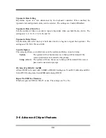
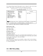
Page 28: ...F1 General Help F5 Previous Values F6 Optimized Defaults F7 Standard Defaults Note Change these settings only if you are familiar with the chipset DRAM Timing Setting Please refer to section 3 6 1 AG...

Page 29: ...alled the number of clock cycles of CAS latency depends on the DRAM timing The settings are 2T 2 5T and 3T RAS Precharge Time If an insufficient number of cycles is allowed for the RAS to accumulate i...

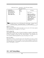
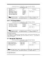
Page 30: ...Post Write Disabled PCI Delay Transaction Enabled Menu Level Move Enter Select PU PD Value F10 Save ESC Exit F1 General Help F5 Previous Values F6 Optimized Defaults F7 Standard Defaults PCI Delay Tr...

Page 31: ...er Access Enabled IDE Prefetch Mode Enabled IDE HDD Block Mode Enabled Delay For HDD Secs 0 Menu Level Move Enter Select Item PU PD Value F10 Save ESC Exit F1 General Help F5 Previous Values F6 Optimi...

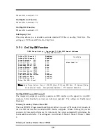
Page 32: ...p Device Function Item Help RealTek LAN Function Enabled RealTek LAN BootROM Disabled AC97 Sound Device Auto USB Device Function Disabled Game Port Address 200 Midi Port Address Disabled Midi Port IRQ...

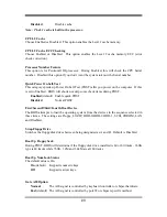
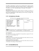
Page 33: ...river the driver is in CD Pack VIA VIAFIR Onboard Parallel Port There is a built in parallel port on the on board Super I O chipset that Provides Standard ECP and EPP features It has the following opt...

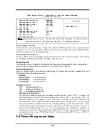
Page 34: ...bled the Advanced Configuration and Power Management ACPI The settings are Enabled and Disabled Video Off Method This determines the manner in which the monitor is blanked V H SYNC Blank This selectio...

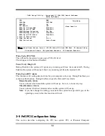
Page 35: ...sabled Power On by Ring LAN During Disabled the system will ignore any incoming call from the modem LAN During Enabled the system will boot up if there s an incoming call from the modem LAN Wake Up on...

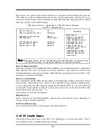
Page 36: ...ts Reset Configuration Data Normally you leave this field Disabled Select Enabled to reset Extended System Configuration Data ESCD when you exit Setup if you have installed a new add on and the system...

Page 37: ...ock is 133MHz DRAM Clock at Next Boot is 133MHz 2 5V Select 2 65V Menu Level Move Enter Select Item PU PD Value F10 Save ESC Exit F1 General Help F5 Previous Values F6 Optimized Defaults F7 Standard D...

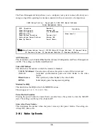
Page 38: ...ou will be asked to confirm the password Type the password again and press Enter You may also press Esc to abort the selection and not enter a password To disable a password just press Enter when you...

Page 39: ...u may make 10 selections 1 VIA 4 IN 1 install VIA Service Pack 4 IN 1 driver 2 VGA install VIA VGA driver 3 SOUND install ALC Audio Codec driver 4 LAN install RT810X LAN Controller driver 5 USB2 0 ins...

Page 40: ...NCE INF VIA REGISTRY DRIVER IS TO BE INSTALLED UNDER WINDOWS THE DRIVER WILL ENABLE VIA POWER MANAGERMENT CONTROLLER 1 Click IDE when MAGIC INSTALL MENU appears 2 Click NEXT when VIA Service Pack Wiza...

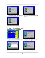
Page 41: ...port Driver 9 Click Finish to restart computer 4 2 VGA install VIA VGA Driver For WINDOWS 9X ME NT4 0 2000 XP 1 Click VGA when MAGIC INSTALL MENU appears 2 Click NEXT When ProSavageDDR Driver Install...

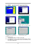
Page 42: ...s 4 Click Start Program Avance Sound Manager AvRack Then AVRACK Windows appears 5 Sound Effect select and KaraOK Mode Function 6 Manual Sound Effect Setting Note The path of the file For WIN98 NT4 0 W...

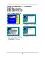
Page 43: ...WINDOWS 2000 is X RTLLAN WIN2000 for WINDOWS XP is X RTLLAN WINXP WINDOWS 98SE 98ME 2000 XP Setup 1 Click LAN when Magic Install Menu appears 2 Click NEXT when Realtak InstallShied Wizard appears 3 Wi...

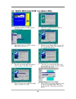
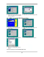
Page 44: ...on you will have this picture choose from internet you can upgrade BIOS On line 5 When On line update BIOS the program will auto check your BIOS version 6 Click Next if you need update BIOS after upgr...

Page 45: ...e to update BIOS 4 6 USB2 0 Install VIA USB2 0 Device Driver 1 Click USB2 0 when MAGIC INSTALL MENU Appear 2 When USB2 0 Setup Program Appear Click NEXT 3 Select Install USB Driver and Click NEXT 4 Se...

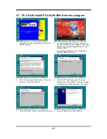
Page 46: ...NEXT when Install Shield Wizard For PC CILLIN 2002 2 Click Open Manual you can learn PC CILLIN 2002 how to use 3 This is license agreement select I Accept the terms and Click NEXT 4 Click NEXT and En...

Page 47: ...trol of BIOS SETUP Otherwise the system the will not allow you to upgrade BIOS by Award Flash Utility Method 1 Use Magic BIOS update BIOS in Windows 98 refer page 41 Method 2 In DOS Mode STEP 1 Prepar...

Reviews: