background image


56


4-10      HOW TO UPDATE BIOS                                         

Before update BIOS please choose Disabled in “Flash Part Write Protect” item on   
“Miscellaneous Control” in BIOS Setup. Please refer to page 

43 

for detail. 

Method 1. 

Use “Magic BIOS” to update BIOS in Windows 98 (refer 

page 53

Method 2. 

In DOS Mode 

STEP 1.


Prepare a boot diskette. (you may make one by clicking START, clicking RUN, 
typing SYS A:, and clicking OK) 

STEP 2.


Copy utility program to your boot diskette.    You may copy from DRIVER CD 

X:\FLASH\AWDFLASH.EXE or download from our web site. 

STEP 3.


Copy the latest BIOS for N2PA-LITE/N2PAP-LITE from our web site to your 
boot diskette. 

STEP 4. 

Insert your boot disc into A:, 
Start the computer and type “Awdflash A:\875PMAXAxxx.BIN /SN/PY/CC/R”   

875PMAXAxxx.BIN is the file name of the latest BIOS it can be 875PMAXA03.BIN 
or 875PMAXB02.BIN 

SN   

means not to save existing BIOS data   


PY      means to renew existing BIOS data 
CC      means to clear existing CMOS data 

R     means to restart computer 

STEP 5. 

Press ENTER and the BIOS will be updated. System will be restarted 
automatically. 


Summary of Contents for 875PMAXR2A

Page 1: ...875PMAX User s Manual Intel Socket 478 Processors Motherboard Intel 875P Intel ICH5 Revision 2 0 P N G03 875PMAX ...

Page 2: ... 2 5 2 2 Installing heatsink cooling fan 11 2 6 Installing System Memory 13 2 6 1 Overview 13 2 6 2 Valid Memory Configurations 13 2 6 3 Installing a DIMM 14 2 6 4 Removing a DIMM 15 2 7 Expansion Cards 15 2 7 1 Procedures for Expansion Cards Installation 15 2 7 2 Assigning IRQs For Expansion Card 16 2 7 3 Interrupt Request Table For This Motherboard 16 2 7 4 AGP Slot 17 2 8 Connectors Headers 18 ...

Page 3: ... Audio Driver 47 4 3 LAN Install Intel Pro 1000 Giga Ethernet Driver 49 4 4 USB 2 0 Install Intel USB 2 0 Driver 49 4 5 SATA Install Promise PDC20378 Serial ATA Controller Driver 50 4 6 RAID Install Promise PDC20378 Fasttrak Controller Driver 51 4 7 PC HEALTH Intel 865 PC Health Monitor 52 4 8 MBIOS DX9 Install BIOS Live Update Utility and DIRECTX9 53 4 9 PC CILLIN Install PC Cillin2002 Anti Virus...

Page 4: ...ks of AMD Corporation Award is a registered trademark of Phoenix Technologies Ltd Intel and Pentium are registered trademarks of Intel Corporation Kensington and MicroSaver are registered trademarks of the Kensington Technology Group Microsoft is a registered trademark of Microsoft Corporation Netware is a registered trademark of Novell Inc NVIDIA the NVIDIA logo DualNet and nForce are registered ...

Page 5: ...e or electrical shock 9 Explosion may occur if the battery is replaced incorrectly Replace only with the type recommended by the manufacturer 10 If one of the following situations arises get the equipment checked by a service personnel a Liquid has penetrated into the equipment b The equipment has been exposed to moisture c The equipment has not work well or you can not get it work according to us...

Page 6: ...mperature Heatsinks induce improved processor heat dissipation through increased surface area and concentrated airflow from attached fans In addition interface materials allow effective transfers of heat from the processor to the heatsink For optimum heat transfer Intel recommends the use of thermal grease and mounting clips to attach the heatsink to the processor When selecting a thermal solution...

Page 7: ...e next generation Intel Prescott CPU when available Dual channel DDR400 memory support Employing the dual channel DDR memory architecture the motherboard provides a solution that doubles the system memory bandwidth to boost system performance The motherboard supports up to 4GB of system memory by using PC3200 2700 2100 non ECC ECC DDR DIMMs to deliver up to 6 4GB s data transfer rate for the lates...

Page 8: ...ogy The CMI8738 6CH hardware AC 97 audio CODEC supports 6 channel 3D surround positioning Audio which is fully compatible with Sound Blaster Pro that gives you the best sound quality and compatibility The motherboard provided SPDIF In SPDIF Out optical function support SPDIF device Adjustable CPU Ratio and Voltage This is a function for user to select preferable multiplying factor for CPU speed in...

Page 9: ...it fixed HDD removable HDD or external HDD This makes multiple operating system environments boot easily for user Once the HDD Boot Sprite is enabled in BIOS your will be prompted with first boot selection menu after POST for friendly operation IEEE 1394 support on 1394 models only The IEEE 1394 interfaces and the VIA 6307 controller onboard provide high speed and flexible PC connectivity to a wid...

Page 10: ...e 32 bit PCI slot x 5 Integrated Storage Supported by South Bridge ICH5 2 x UltraDMA 100 connectors Supported by Promise PDC20378 controller optional 1 x UltraDMA 133 connector 2 x Serial ATA connectors RAID0 RAID1 RAID0 1 configurations Integrated LAN connection Intel 82547EI communications streaming Architecture CSA Interface Gigabit Ethernet GbE controller Supports 10 100 1000 Mb sec data trans...

Page 11: ...438 PC Mark 2002 CPU Memory HDD 7478 7898 891 7525 9328 866 7502 9090 866 Content Creation Winstone 2002 53 54 4 48 9 Content Creation Winstone 2003 52 53 50 9 Business Winstone 2002 33 8 34 9 36 Winbench 99 V1 2 Business Disk Winmark99 8840 9130 9060 Hi end Disk Winmark99 33200 32700 33100 Business Graphic Winmark 559 567 543 Hi end Graphic Winmark 1330 1350 1240 SYS Mark 2001 2002 SISMark 2001 2...

Page 12: ...SYSFAN1 COM2 Connector AGP 8X Slot Floppy Connector Intel 875P Chipset Front Panel Connector ATA 100 IDE Connector Clear CMOS JP3 ATX Power Connector CPU FAN 4MBit FWH BIOS CPU Socket DDR DIMMx4 SYSFAN2 Intel 82801EB Chip Speak Connector Promise PDC20378 Serial ATA Controller ATA 133 IDE Connector Serial ATA Connector SATA4 Serial ATA Connector SATA2 1 USB Port USB Power ON Jumper JP2 GAME Port Co...

Page 13: ...Secondary Third IDE Connector 40 pin Block P 20 SATA1 4 Serial ATA Port Connector 7 pin Block P 21 Headers Header Name Description Page AUDIO Line Out MIC Headers 9 pin Block P 22 USB2 USB Port Headers 9 pin Block P 22 1394A 1394B 1394 Port Headers 9 pin Block P 22 SPEAK Speaker connector 4 pin Block P 22 FP Power LED Reset IDE LED Power Button Front Panel Header including Power LED IDE activity L...

Page 14: ... chassis 3 Place ten 10 screws into the holes indicated by circles to secure the motherboard to the chassis And Do not overtighten the screws Doing so may damage the motherboard 2 2 Before You Proceed Take note of the following precautions before you install motherboard components or change any motherboard settings 1 Unplug the power cord from the wall socket before touching any component 2 Use a ...

Page 15: ... to retain the motherboard configuration in CMOS RAM short 1 2 pins of JP3 to store the CMOS data To clear CMOS follow the procedures below 1 Turn off the system and unplug the AC power 2 Remove ATX power cable from ATX power connector 3 Locate JP3 and short pins 2 3 for a few seconds 4 Return JP3 to its factory setting by shorting pins 1 2 5 Connect ATX power cable back to ATX power connector Not...

Page 16: ...ng Technology and 800 533 400MHz system bus Together these attributes improve system performance by allowing higher core frequencies faster execution of integer instructions and data transfer rates up to 6 4GB s The socket will also support the Intel Prescott CPU when available Note Intel Hyper Threading HT Technology 1 This motherboard supports Intel Pentium 4 CPUs with HT Technology 2 HT Technol...

Page 17: ...lever upward to a 90 degree angle Insert the CPU with the correct orientation as shown below The notched corner should be pointed toward the end of the lever The CPU has corner pin on two of the four corners and the CPU will only fit in the orientation as shown CPU ZIF mPGAB Socket Colden Arrow mPGA478B When you insert the CPU onto the ZIF socket no force is required After inserting press the leve...

Page 18: ...odule base when installing the CPU or installing other motherboard components 2 Your boxed Intel Pentium 4 Processor package should come with installation instructions for the CPU heatsink and the retention mechanism If the instructions in this section do not match the CPU please refer to the installation instructions inside the boxed Intel Pentium 4 Processor package 2 Position the fan with the r...

Page 19: ... occur if you fail to plug this connector 2 6 Installing System Memory 2 6 1 Overview The motherboard comes with four Double Data Rate DDR Dual Inline Memory Module DIMM sockets These sockets support up to 4GB system memory by using 184 pin non ECC PC3200 PC2700 PC2100 DDR DIMMs and allow up to 6 4GB s data transfer rate 2 6 2 Valid Memory Configurations Bank 184 Pin DIMM PCS Total Memory Bank 0 1...

Page 20: ...M2 DIMM4 Dual Channel 2 NOTE When you install DIMM module fully into the DIMM socket the eject tab should be locked into the DIMM module very firmly and fit into its indention on both sides WARNING For the DDR SDRAM CLOCK is set at 200MHz use only DDR400 compliant DDR Modules When this motherboard operate at 200Mhz most system will not even boot if non compliant modules are used because of the str...

Page 21: ...ailing to do so may cause severe damage to both the motherboard and expansion cards 2 7 1 Procedures for Expansion Cards Installation 1 Read the documentation of the expansion card and make any necessary hardware or software setting on the expansion card such as jumpers before installing 2 Remove computer cover and the bracket plate on the slot you intend to use 3 Align the card s connectors and p...

Page 22: ... for PCI Steering 11 2 IRQ Holder for PCI Steering 12 4 PS 2 Compatible Mouse Port 13 N A Numeric Data Processor 14 5 Primary IDE Channel 15 1 Secondary IDE Channel These IRQs are usually available for ISA or PCI devices 2 7 3 Interrupt Request Table For This Motherboard Interrupt requests are shared as shown in the table below INT A INT B INT C INT D PCI slot 1 Shared PCI slot 2 Shared PCI slot 3...

Page 23: ...X notch show below please make sure your AGP card is AGP 4X 8X 1 5V 0 8V not AGP 2X 3 3V AG PSLO T Example 1 SiS 305 ATi Rage 128 Pro AGP card those golden finger is compatible with 2X 4X mode AGP slot but only can support 2X 3 3V only If you install these cards in Intel 865 based motherboard it will burn and damage the motherboard Example 2 We also find Diamond Vipper V770 golden finger is design...

Page 24: ...front panel switch is momentarily pressed Press this switch again will turn off the power to the system board PIN ROW2 ROW1 1 3 3V 3 3V 2 12V 3 3V 3 GND GND 4 Soft Power On 5V 5 GND GND 6 GND 5V 7 GND GND 8 5V Power OK 9 5V 5V for Soft Logic 10 5V 12V Pin 1 2 ATX 12V Power Connector 4 pin block ATX12V This is a new defined 4 pins connector that usually comes with ATX Power Supply The ATX Power Sup...

Page 25: ...rd Parallel Port can be disabled through the BIOS SETUP Please refer to Chapter 3 INTEGRATED PERIPHERALS SETUP section for more detail information 8 Audio Line In Lin Out MIC Connector CN1 This Connector are 3 phone Jack for LINE OUT LINE IN MIC Line out Audio output to speaker Line in Audio input to sound chip MIC Microphone Connector 9 Serial Port COM1 COM2 COM1 COM2 COM1 COM2 is the 9 pin D Sub...

Page 26: ...ingly Please refer to the documentation of your hard disk for the jumper settings 12 Secondary IDE Connector 40 pin block IDE2 This connector connects to the next set of Master and Slave hard disks Follow the same procedure described for the primary IDE connector You may also configure two hard disks to be both Masters using one ribbon cable on the primary IDE connector and another ribbon cable on...

Page 27: ...DE3 14 Serial ATA Port connector SATA1 SATA2 SATA3 SATA4 This connector support the provided Serial ATA IDE hard disk cable to connecting the motherboard and serial ATA hard disk Serial ATA Port Connector Pin 1 SATA2 SATA1 SATA4 SATA3 On Chip Serial ATA Promise Serial ATA 2 8 2 Headers 1 Line Out MIC Header 9 pin AUDIO This header connect to Front Panel Line out MIC connector with cable Line Out M...

Page 28: ...o the hard disk activity indicator light on the case 5 Reset switch lead RESET This 2 pin connector connects to the case mounted reset switch for rebooting your computer without having to turn off your power switch This is a preferred method of rebooting in order to prolong the lift of the system s power supply See the figure below 6 Speaker connector SPEAK This 4 pin connector connects to the cas...

Page 29: ...d through the LAN card NOTE This feature requires that Wake On LAN or Ring In Wake up is enabled Wake On LAN Headers WOL 1 3 5VSB G ND WO L 10 FAN Speed Headers 3 pin SYSFAN1 SYSFAN2 CPUFAN These connectors support cooling fans of 350mA 4 2 Watts or less depending on the fan manufacturer the wire and plug may be different The red wire should be positive while the black should be ground Connect the...

Page 30: ... IR infrared module Headers IR Pin1 G ND IR RX NC VCC 5 IRTX 2 5 6 12 CD Audio In Headers 4 pin CDIN CDIN are the connectors for CD Audio Input signal Please connect it to CD ROM CD Audio output connector CD Audio In Headers C DIN 1 4 13 Game Port Header GAME Pin 1 GAME Port Headers 14 Optical In Out Header JP7 SPDIF Bracket Connector Pin1 JP6 NC SPDIF O UT NC G ND 12V G ND NC SPDIF IN2 SPFIF IN1 ...

Page 31: ...e system will then run power on test While the test are running the BIOS will alarm beeps or additional message will appear on the screen If you do not see any thing within 30 seconds from the time you turn on the power The system may have failed on power on test Recheck your jumper settings and connections or call your retailer for assistance Beep Meaning One short beep when displaying logo No er...

Page 32: ...as shown in Figure 3 1 These options will be explained step by step in the following pages Before going further let us first take a short look at the descriptions of the function keys you may use here Press Esc to quit the BIOS Setup Press up down left right to choose in the main menu the option you want to confirm or to modify Press F10 to save these parameters and to exit the BIOS Setup menu whe...

Page 33: ...creen There are fourteen setup functions and two exit choices allowing you to select under the Main Menu Use arrow keys to select among the items and press Enter to accept or enter the sub menu CMOS Setup Utility Copyright C 1984 2003 Award Software Standard CMOS Features Advanced BIOS Features Advanced Chipset Features Integrated Peripherals Power Management Setup PnP PCI Configurations PC Health...

Page 34: ...pears if your system supports PnP PCI PC Health Status This entry shows your PC health status Miscellaneous Control Use this menu to specify your settings for Miscellaneous Control Load Optimized Defaults Use this menu to load the BIOS default values that are factory set for optimal system performances operation Load Standard Defaults Use this menu to load the BIOS default values for the minimal s...

Page 35: ...y of the week from Sun to Sat determined by BIOS Read only Month The month from Jan through Dec Date The date from 1 to 31 can be keyed in using numeric function keys Year The year depends on the year of the BIOS Time The time format is hour minute second Primary Master Primary Slave Secondary Master Secondary Slave Press PgUp or PgDn to select Manual None Auto type Note that the specifications of...

Page 36: ...s Sec 6 Typematic Delay Msec 250 Security Option Setup APIC Mode Disabled MPS Version Control For OS 1 4 OS Select For DRAM 64MB Non OS2 Menu Level Move Enter Select PU PD Value F10 Save ESC Exit F1 General Help F5 Previous Values F6 Optimized Defaults F7 Standard Defaults Anti Virus Protection Allows you to choose the VIRUS Warning feature for IDE Hard Disk boot sector protection If this function...

Page 37: ... selected in these items The settings are Floppy LS ZIP HDD 0 HDD 1 HDD 3 SCSI CDROM LAD and Disabled Swap Floppy Drive Switches the floppy disk drives between being designated as A and B Default is Disabled Boot Up Floppy Seek During POST BIOS will determine if the floppy disk drive installed is 40 or 80 tracks 360K type is 40 tracks while 760K 1 2M and 1 44M are all 80 tracks Boot Up NumLock Sta...

Page 38: ...S2 to be used with 64MB or DRAM Settings are Non OS 2 default and OS2 Set to OS 2 if using more than 64MB and running OS 2 3 7 Advanced Chipset Features The Advanced Chipset Features Setup option is used to change the values of the chipset registers These registers control most of the system options in the computer CMOS Setup Utility Copyright C 1984 2003 Award Software Advanced Chipset Features I...

Page 39: ...t need to use this area of system memory usually discusses their memory requirements The settings are Enabled and Disabled Delay Transaction The chipset has an embedded 32 bit posted write buffer to support delay transactions cycles Select Enabled to support compliance with PCI specification version 2 1 The settings are Enabled and Disabled AGP Transfer Mode In this item you can select AGP transfe...

Page 40: ...and Slow gives more stable performance This field applies only when synchronous DRAM is installed in the system The settings are 2T 3T and 4T 3 8 Integrated Peripherals CMOS Setup Utility Copyright C 1984 2003 Award Software Integrated Peripherals Item Help Onboard IDE Function Press Enter Onboard Device Function Press Enter Onboard Super IO Function Press Enter Init Display First PCI Slot Power O...

Page 41: ...ngs are Enabled and Disabled Primary Secondary Master Slave PIO The four IDE PIO Programmed Input Output fields let you set a PIO mode 0 4 for each of the four IDE devices that the onboard IDE interface supports Modes 0 through 4 provide successively increased performance In Auto mode the system automatically determines the best mode for each device The settings are Auto Mode 0 Mode 1 Mode 2 Mode ...

Page 42: ...Address Midi Port IRQ 10 Menu Level Move Enter Select PU PD Value F10 Save ESC Exit F1 General Help F5 Previous Values F6 Optimized Defaults F7 Standard Defaults CMI8738 Sound Chip This will determine which on Board Sound Chip Function will use The settings are Enabled Disabled Promise378 Operation Mode Select RAID Mode if you want to use the RAID function in Serial ATA drive The settings are SATA...

Page 43: ...ard and you wish to use it If you install add on FDC or the system has no floppy drive select Disabled in this field The settings are Enabled and Disabled Onboard Serial Port 1 Port 2 Select an address and corresponding interrupt for the first and the second serial ports The settings are 3F8 IRQ4 2E8 IRQ3 3E8 IRQ4 2F8 IRQ3 Disabled Auto UART2 Mode Select This item allows you to determine which Inf...

Page 44: ...llows you to configure your system to most effectively save energy saving while operating in a manner consistent with your own style of computer use CMOS Setup Utility Copyright C 1984 2003 Award Software Power Management Setup Item Help ACPI Function Enabled ACPI Suspend Type S1 POS Power Management User Define Video off Method V H SYNC Blank Video Off In Suspend Yes Suspend Type Stop Grant MODEM...

Page 45: ...the system to enter the Soft Off state The settings are Delay 4 Sec Instant Off Wake Up by PCI card Power On by Ring During Disabled the system will ignore any incoming call from the PCI card modem During Enabled the system will boot up if there s an incoming call from the PCI card modem Wake Up on RTC Alarm This function is for setting date and time for your computer to boot up During Disabled yo...

Page 46: ...nal Computer Interconnect is a system which allows I O devices to operate at speeds nearing the speed the CPU itself uses when communicating with its own special components This section covers some very technical items and it is strongly recommended that only experienced users should make any changes to the default settings CMOS Setup Utility Copyright C 1984 2003 Award Software PnP PCI Configurat...

Page 47: ...he sub menu that follows this field a sub menu is preceded by a The settings are Auto ESCD Manual IRQ Resources When resources are controlled manually assign each system interrupt a type depending on the type of device using the interrupt Please refer to section 3 9 1 PCI VGA Palette Snoop Leave this field at Disabled The settings are Enabled Disabled 3 10 1 IRQ Resources CMOS Setup Utility Copyri...

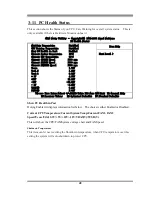
Page 48: ...rpm Vcore 1 71V Vcc1 5 1 51V Vcc3 3 3 31V 5V 4 98V 12V 12 22V 12V 12 36V 5V 4 99V VBAT V 3 21V 5VSB V 5 02V Menu Level Move Enter Select PU PD Value F10 Save ESC Exit F1 General Help F5 Previous Values F6 Optimized Defaults F7 Standard Defaults Show PC Health in Post During Enabled it displays information list below The choice is either Enabled or Disabled Current CPU Temperature Current System Te...

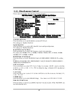
Page 49: ...lock and Spread Spectrum The settings are Enabled Disabled Host PCI Clock at Next Boot This item allows you to select CPU frequency step by step increasing The choice are 400MHz CPU 100MHz 350MHz 533MHz CPU 133MHz 350MHz 800MHz CPU 200MHz 350MHz DRAM Clock at Next Boot is This item allows you select the DRAM Clock for DDR266 DDR333 DDR400 The setting are DDR266 for P4 400MHz CPU DDR266 DDR333 for ...

Page 50: ...up to eight characters in length and press Enter The password typed now will clear any previously entered password from CMOS memory You will be asked to confirm the password Type the password again and press Enter You may also press Esc to abort the selection and not to enter a password To disable a password just press Enter when you are prompted to enter the password A message will confirm that t...

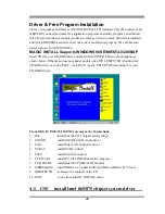
Page 51: ...pear as shown below If the menu does not appear double click MY COMPUTER double click CD ROM drive or click START click RUN type X SETUP EXE assuming X is your CD ROM drive From MAGIC INSTALL MENU you may make 10 selections 1 INF install Intel 865 875 chipset system driver 2 SOUND install CMI8738 6CH Audio driver 3 LAN install Intel LAN Controller driver 4 USB2 0 install USB 2 0 driver 5 SATA inst...

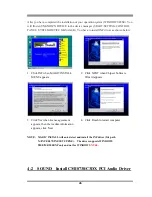
Page 52: ...Click INF when MAGIC INSTALL MENU appears 2 Click NEXT when Chipset Software Wizard appears 3 Click Yes when license agreement appears then the readme information appears click Next 4 Click Finish to restart computer NOTE MAGIC INSTALL will auto detect and install the INF driver file path X INTEL875 INF SETUP EXE The driver supports WINDOWS 98SE ME 2000 XP only and not for WINDOWS NT4 0 4 2 SOUND ...

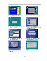
Page 53: ... and Click OK 4 Click Next when copyright Issue appears click Next or choose BROWSE to change the path for the file to be store 5 Choose another Program Folders for installing or click Next 6 OS will auto detect and set up C Media CMI8738 C3DX PCI Audio Device 7 Select 2 4 5 1 Channel speaker output and Click EXIT 8 Click YES and restart computer ...

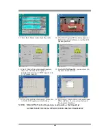
Page 54: ...ion setting S PDIF supports only 2 CH speaker output 12 Enable USING Xear 3D you can select 4 6 Speakers Xear Functions 13 Click C Media Mixer Advanced volume this is for the 6CH speaker volume Setting 14 By clicking C Media Mixer Advanced Sound Effect selection You can set up the Sound Environment Simulator NOTE MAGIC INSTALL will auto detect and install or the file path is X CMI8738 SETUP EXE fo...

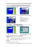
Page 55: ...se agreement menu appears click Yes then finish installing driver click Close and restart your computer Windows 2000 XP USB 2 0 Driver installation Windows 2000 Mothed1 Start Windows 2000 OS and Internet Connect Select Windows Update Select Driver Update Install Windows2000 USB2 0 Driver Mothed2 Install Windows 2000 Service Pack 4 or later Windows XP Install Windows XP Service Pack 1 or later 3 Se...

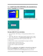
Page 56: ...ct Driver Update Driver Change the directory to X SATA378 SATA WINXP then select OK It will auto detect WinXP Promise SATA378 tm IDE Controller driver The path of the file For Windows 9X is X SATA378 SATA WIN98 ME including Win95 98 ME For Windows NT4 0 is X SATA378 SATA NT4 For Windows 2000 is X SATA378 SATA WIN2000 For Windows XP is X SATA378 SATA WINXP NOTE When you try to install Window NT4 0 ...

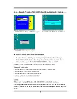
Page 57: ...ange the directory to X SATA378 RAID WINXP then select OK It will auto detect WinXP Promise FastTrak 376 378 tm Controller driver The path of the file For Windows 9X is X SATA378 RAID WIN98 ME including Win95 98 ME For Windows NT4 0 is X SATA378 RAID NT4 For Windows 2000 is X SATA378 RAID WIN2000 For Windows XP is X SATA378 RAID WINXP NOTE When you try to install Window NT4 0 2000 XP OS with RAID ...

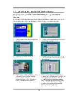
Page 58: ...ntinue installation 4 Select Program Group or enter a new group click Next and then click Finish to complete the installation 5 Click Program Winbond Hardware Doctor Hardware Doctor then the Winbond Hardware Doctor will appears You can remove the Utility from Control Panel Add Remove Program icon 6 After executing Winbond Hardware Doctor system voltage Fan speed and CPU SYSTEM Temperature can be d...

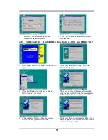
Page 59: ...2 Click Next to install the Magic BIOS in Destination Folder 3 After finish Setup you will have a Magic BIOS icon on your screen 4 The above picture will appear after double click the Magic BIOS icon You can upgrade BIOS On line by choose internet 5 When updating BIOS on line the program will auto check your BIOS version 6 Click Next if you need to update BIOS After BIOS is updated the system will...

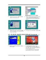
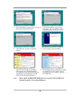
Page 60: ... to update BIOS you must have the correct BIOS file in your Local Driver 10 Choose the correct BIOS file to update BIOS 4 9 PC CILLIN Install PC CILLIN 2002 Anti virus program 1 Click PC CILLIN when MAGIC INSTALL MENU appears 2 1 Click Install PC CILLIN when PC CILLIN 2002 main menu appears and click NEXT when Install Shield Wizard For PC CILLIN 2002 shows up 2 Click Open Manual and you can learn ...

Page 61: ...nd click FINISH 7 After PC CILLIN 2002 set up complete Please register your information and get LICENSE KEY from TREND MICRO web site then enter your license key and click FINISH to exit the registration menu 8 After finishing register procedures we highly recommend you to select update item for downloading the newest engine codes and virus definitions Note Please install ACROBAT READER before you...

Page 62: ...oot diskette You may copy from DRIVER CD X FLASH AWDFLASH EXE or download from our web site STEP 3 Copy the latest BIOS for N2PA LITE N2PAP LITE from our web site to your boot diskette STEP 4 Insert your boot disc into A Start the computer and type Awdflash A 875PMAXAxxx BIN SN PY CC R 875PMAXAxxx BIN is the file name of the latest BIOS it can be 875PMAXA03 BIN or 875PMAXB02 BIN SN means not to sa...

Page 63: ...single drive but at a sustained data transfer rate double that of a single disk alone thus improving data access and storage RAID 1 called data mirroring copies and maintains an identical image of data from one drive to a second drive If one drive fails the disk array management software directs all applications to the surviving drive as it contains a complete copy of the data in the other drive T...

Page 64: ...tion 1 Set the jumpers of each hard disk as Master Slave 2 Install the hard disks into the drive bays 3 Connect the HDD cables These connection options are available for creating a RAID 0 or RAID 1 array a Connect two Parallel ATA HDDs to PRI_RAID1 connector and one Serial ATA HDD to either one of the two Serial ATA connectors using separate parallel ATA or serial ATA cables b Connect one Serial A...

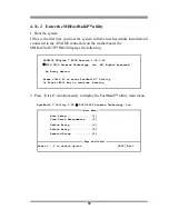
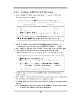
Page 65: ... TX2plus BIOS Version 1 00 0 23 2002 2005 Promise Technology Inc All Rights reserved No Array defind Press Ctrl F to enter FastBuild Utility Or Press ESC key to continue booting 2 Press Ctrl F simultaneously to display the FastBuild utility main menu FastBuild Utility 2 00 2002 2005 Promise Technology Inc Auto Setup 1 View Drive Assignments 2 Define Array 3 Delete Array 4 Rebuild Array 5 Press 1 5...

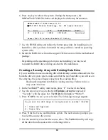
Page 66: ...system During the boot process the MBFastTrak378 BIOS checks and displays the disk array information MBFastTrak378 BIOS Version 1 00 2002 2005 Promise Technology Inc All Rights Reserved ID Mode SIZE TRACK MAPPING STATUS 1 2 0 Stripe 240068M 29186 255 63 Function Press Ctrl F to enter Fastbulid Utility 5 Once the array is created use the FDISK utility to format the array as a single hard drive 6 Af...

Page 67: ... Change Option ESC Exit CTRL Y Save Use the arrow keys to go to the field Optimize Array for and select Security with the space bar The Mode field displays Mirror 3 Press Ctrl Y to save your selection 4 The following message appears Do you want disk image to be duplicated to another Yes No Y Create and Duplicate N Create Only 5 Press N for the Create Only option A message appears confirming that y...

Page 68: ... Existing Data Drive If you would like to use an existing drive that already contains data and or is the bootable drive in your system make sure that the new hard drive you will use in the array has the same or larger capacity as the existing drive Backup all important data before creating an array Failure to do so may cause data loss 1 In the FastBuild utility main menu press 1 to select Auto Set...

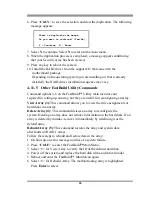
Page 69: ...g up an array but they are useful for reconfiguring an array View Array 3 This command allows you to view the drive assignments of hard disks in an array Delete Array 4 This command deletes an array to reconfigure the system Deleting an array does not remove information on the hard disks If an array is deleted by mistake recover it immediately by redefining it as the deleted array Rebuild Array 5 ...

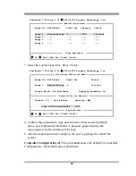
Page 70: ...ble Gigabyte Boundary On Channel ID drive Model Capacity MB 3 Mas FUJITSU MPD3043AT 4325 Up Down ESC Exit Enter Select 8 Confirm the command to copy data from the intact source hard disk onto a new replacement hard disk A progress gauge displays the copy progress for the duration of the task 9 After the rebuild processis complete the user is prompted to reboot the system Controller Configuration 6...

Reviews: