11
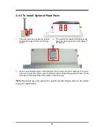
Notice: When lifting the cover up to open the chassis for further installation, see to it that
the connecting cables are not unplugged. It is very important for the cables connected to
their original places for normal functioning.
2-3 Jumper Settings
Jumper is a small component consisting of jumper clip and jumper pins. Install
jumper clip on 2 jumper pins to close the pins. And remove jumper clip from 2
jumper pins to open the pins. Diagram 2-1 illustrates how to set up a jumper.
JP1 (3-pin): INVERTER VLED 5V/12V Select
2-3 Closed: Inverter VLED= 12V.
JP1
→
INVERTER
1-2 Closed: Inverter VLED= 5V;
1
3
1
3
JPCOM1 (4-pin): COM1 Header Pin9 Function Select
JCOMP1
→
COM1 Header
4-6 Closed:
RI= 12V.
1
3
5
3-4 Closed:
RI= 5V;
2-4 Closed:
RI=RS232;
4
6
2
6
5
3
1
4
2
5
3
1
6
4
2


