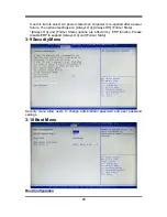
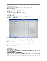
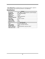
background image


34 


Electronic Emissions Notices 

European Union Compliance Statement Class B Compliance 

European Union – Compliance to the Electromagnetic Compatibility Directive 


This product is in conformity with the protection requirements of EU Council Directive 2004/108/EC on 

the  approximation  of  the  laws  of  the  Member  States  relating  to  electromagnetic  compatibility.  We 

cannot  accept  responsibility  for  any  failure  to  satisfy  the  protection  requirements  resulting  from  a 

non-recommended  modification  of  the  product,  including  the  installation  of  option  cards  from  other 

manufacturers. 

This  product  has  been  tested  and  found  to  comply  with  the  limits  Class  B  Information  Technology 

Equipment according to European Standard EN55022. The limits for Class B equipment were derived 

for typical residential environments to provide reasonable protection against interference with licensed 

communication devices. 


Properly shielded and grounded cables and connectors must be used in order to reduce the potential 

for  causing  interference  to  radio  and  TV  communications  and  to  other  electrical  or  electronic 

equipment. 


FCC Rules and Regulations-Part 15 

This  devices  uses,  generates  and  radiates  radio  frequency  energy.  The  radio  frequency  energy 

produced by this device is well below the maximum exposure allowed by the Federal Communications 

Commission (FCC) 


This device complies with the limits for the Class B digital device pursuant to Part 15 subject to the 

following two conditions: 


This device may not cause harmful interference. 


This  device  must  accept  any  interference  received,  including  interference  that  may  cause 

undesired operation. 

The FCC limits are designed to provide reasonable protection against harmful interference when the 

equipment  is  installed  and  used  in  accordance  with  the  instruction  manual  and  operated  in  a 

commercial environment. However, there is no guarantee that interference will not occur in a particular 

commercial installation, or if operated in a residential area. 

If harmful interference with radio or television reception occurs when the device is turned on, the user 

must correct the situation at the user’s own expense. The user is encouraged to try one or more of the 

following corrective measures: 


Re-orient or relocate the receiving antenna. 


Increase the separation between the equipment and receiver. 


Connect  the  equipment  into  an  outlet  on  a  circuit  different  from  that  on  which  the  receiver  is 

connected. 


Consult the dealer or an experienced radio/TV technician for help. 

CAUTION: 

The  Part  15  radio  device  operates  on  a  non-interference  basis  with  other  devices 

operating  at  this  frequency.  Any  changes  or  modification  to  said  product  not  expressly  approved  by 

Intel could void the user’s authority to operate this device. 


Summary of Contents for HPC070SC-FP2807A Series

Page 1: ...Panel PC User s Manual NO G03 PCNP93CFP F Manual Revision 1 0 Release Date April 18 2018...

Page 2: ...2 To Open the Chassis 10 2 3 Jumper Settings 11 2 4 Hardware Installation 14 2 4 1 To install MSATA Card 14 2 4 2 To install Wireless LAN Card 15 2 4 3 To install Optional Fixed Parts 17 Chapter 3 In...

Page 3: ...e sure to set up or use the product on a stable surface Make sure not to drop the product or strike it by any means Make sure not to move the product when the power is on Make sure not to step on the...

Page 4: ...arranty of any kind and will not be liable for any indirect special incidental or consequential damages including damages for loss of profit loss of business loss of use of data interruption of busine...

Page 5: ...ideo output Support RS232 422 485 serial port The system has the following features besides other basic functions WiFi the Mini PCI E onboard socket in the board is integrated a with a WiFi card 802 1...

Page 6: ...MHz SO DIMM BIOS AMI 64Mb Flash ROM I O System Standard I O For HPC070SC FP2807A Series 1 Euro terminal block by 12V DC input 1 USB3 0 1 USB2 0 port 1 RJ 45 LAN port for Gigabit Ethernet 1 HDMI port 1...

Page 7: ...Rear IO Q ty DC in Jack 1 USB2 0 1 USB3 0 1 RJ 45 1 HDMI 1 RS232 422 485 1 RS232 N A Power Button 1 For HPC 080SC FP2807A HPC 080SC FP2930A Series Bottom View Rear IO Q ty DC in Jack 1 USB2 0 3 USB3...

Page 8: ...is any differences that we do not cover please refer to the actual product you purchase 2 Model HPC 080SCSC FP2807A HPC 080SCSC FP2930A series share the same IO specifications as the above diagram sh...

Page 9: ...connector is standard RJ 45 LAN jack for Network connection DC in Power Connector For user to connect compatible terminal power block to provide power supply for the system 2 I O Connectors Pin Defini...

Page 10: ...ed by plugging one end of the Ethernet cable into this RJ 45 connector and the other end phone jack to a 1000 100 10 Base T hub The pin assignment for RJ 45 Ethernet LAN connectors are listed as follo...

Page 11: ...7 Chapter 2 Hardware and Installation 2 1 Dimension and Outlines Product Dimension for HPC070SC FP2807A Series Measure Unit mm...

Page 12: ...8 Product Dimension for HPC 080SC FP2807A HPC 080SC FP2930A Series Measure Unit mm...

Page 13: ...9 Product Dimension for HPC 080SC 2807A Series Measure Unit mm...

Page 14: ...pen the Chassis Use a screwdriver to unscrew the screws marked above that lock the back cover see red circles Remove them to open the chassis HPC070SC FP2807A HPC 080SC FP2807A HPC 080SC FP2930A HPC 0...

Page 15: ...t consisting of jumper clip and jumper pins Install jumper clip on 2 jumper pins to close the pins And remove jumper clip from 2 jumper pins to open the pins Diagram 2 1 illustrates how to set up a ju...

Page 16: ...3 3V 6 4 2 6 4 2 3 3 3 1 5 1 5 1 5 Pin 1 3 of J1 10 pin Clear CMOS Setting Pin 1 3 of J1 Clear CMOS Setting Pin 1 1 3 Closed Clear CMOS 1 3 Open Normal Pin 1 2 2 9 10 9 10 Pin 5 7 of J1 10 pin Clear M...

Page 17: ...utton to power on after power input ready AT Mode Selected Directly power on as power input ready Pin 6 8 of J1 10 pin Security Management Engine Function Select Pin 6 8 of J1 Didable ME Select Pin 1...

Page 18: ...Card 1 Place the Panel PC with this side up upon a flat operation platform See to it to put a protective cushion under the panel to prevent possible damage 2 Remove the screws that lock the chassis o...

Page 19: ...Wireless LAN Card Please refer to the following instructions for the installation of the wireless LAN card 1 Locate the Mini PCIE card slot on the board 2 Remove the marked screw and use it to lock WI...

Page 20: ...tenna string are sealed by acetate tape to avoid possible damage to the system 6 Tear off the tape to find metal hats of WiFi antenna string 7 Press the metal hats on the end of the antenna string to...

Page 21: ...reserved on both sides of the system 3 Insert corresponding edges of the fixed part into the slots until them matched The screw is for user to lock the system upon the platform with corresponding pun...

Page 22: ...s the entire hardware device and configures the parameters of the hardware synchronization Only when these tasks are completed done it gives up control of the computer to operating system OS Since the...

Page 23: ...creen Press up down to choose in the main menu the option you want to confirm or to modify Press Enter to select Press keys when you want to modify the BIOS parameters for the active option F1 General...

Page 24: ...t To change chipset configuration Security Password settings Boot To change boot settings Save Exit Save setting loading and exit options User can press the right or left arrow key on the keyboard to...

Page 25: ...d The optional settings are Suspend Disabled S3 Suspend to RAM Super I O Configuration Press Enter to make settings for the following sub items Super IO Configuration Serial Port 1 Configuration Press...

Page 26: ...m support WDT wake up while ERP function is set as Enabled The optional settings are Enabled Disabled When set as Enabled the following sub items shall appear WatchDog Timer Value in ERP User can sele...

Page 27: ...Resolution The optional settings are 80x24 80x25 Putty Keypad The optional settings are VT100 LINUX XTERMR6 SCO ESCN VT400 Redirection After BIOS POST The optional settings are Always Enable BootLoad...

Page 28: ...The optional settings are Disabled 70 o C 156 o F 75 o C 164 o F 80 o C 172 o F 85 o C 180 o F 90 o C 188 o F CPU Configuration Press Enter to view current CPU configuration and make settings for the...

Page 29: ...e optional settings are Enabled Disabled When set as Enabled the following sub items shall appear Ipv4 PXE Support The optional settings are Disabled Enabled Use this item to enable Ipv4 PXE Boot Supp...

Page 30: ...Press Enter to make settings for the following sub items USB Configuration Legacy USB Support The optional settings are Enabled Disabled Auto Enabled To enable legacy USB support Disabled To keep USB...

Page 31: ...er 3 8 Chipset Menu North Bridge Press Enter to view current using memory information and make settings for the following sub items PAVC Use this item to enable or disable Protected Audio Video Contro...

Page 32: ...bit 1600 x 900 24 bit 1680 x 1050 24 bit 1600 x 1200 24 bit 1920 x 1080 24 bit South Bridge Press Enter to make further setting in the following sub items Mini PCIE The optional settings are Enabled D...

Page 33: ...ettings are Always On Always Off Former State Always On and Former State options are affected by ERP function Please disable ERP to support Always On and Former State 3 9 Security Menu Security menu a...

Page 34: ...m after saving the changes Discard Changes and Reset This item allows user to reset the system without saving any changes Restore Defaults Use this item to restore load default values for all the setu...

Page 35: ...itive type Active Range 152 40 x 91 44mm 0 2mm Transparency 85 Surface Hardness 6H JIS 5400 Glass haze value 3 HPC080SC FP2807A HPC080SC FP2930A is designed based on the technology of of projected cap...

Page 36: ...on metal front bazel Display Type 8 with LED backlight Brightness 400 nits Display Color 16 7M Resolution 1024 x 768 60Hz Viewing Angle H V 160o 160 o Pixel Pitch 0 158 x 0 158 mm Aspect Ratio 4 3 Con...

Page 37: ...Fi Alliance Usage Environment and Your Health Wireless LAN PCI Express Mini Card emits radio frequency electromagnetic energy like other radio devices However the level of energy emitted is far much l...

Page 38: ...imum exposure allowed by the Federal Communications Commission FCC This device complies with the limits for the Class B digital device pursuant to Part 15 subject to the following two conditions This...

Reviews: