background image


1

Chapter 1


Introduction


1-1 General Descriptions


Thank  you  for  purchasing  the  system,  a  new  product  developed,  designed  and 
manufactured  under  leading  technical  power  and  consistent  dedication  to  fine 
workmanship. 


A true flat, easy-to-clean front surface with esge-to-edge design


Streamlined enclosure for highly efficient heat dissipation enclosed in robust 

aluminum casing


Strong solid aluminum frame design and fanless cooling system


Support open frameless design


Designed for mounting clips and VESA mount installation


IO ports designed for easy connection


IP65-rated front bezel against water and dust (150/170/185 series)


Onboard  Intel®  

Bay  Trail  series  SoC  processor,  with  low  power 

consumption never denies high performance


Onboard 4GB DDR3L 1333Mhz SO-DIMM


Support 1 * 2.5" SATA HDD Device, 1* Mini PCIe, 1* M.2 connector


Support dual Gigabit LAN


Support 4G SIM card socket


Support 802.11 b/g/n WiFi communication  


Support VGA output 


Support multiple COM ports


The system has the following features besides other basic functions:


WiFi: 

the  Mini  PCI-E  onboard  socket  in  the  board  is  integrated  a  with  a  WiFi 

card(802.11  b/g/n)  that  can  act  as  a  mini  wireless  modem  when  external 
antennas  are  connected.  Different  computers  in  the  house  can  build  wireless 
connections through the Mini TOP system and take necessary data from it, thus 
reducing the complexity in network establishment. 


Giga  LAN

:  The  system  is  integrated  with  Gigabit  LAN  network  controller  with 

ACPI  management  realizing  efficient  power  management  for  the  operating 
system. 


USB3.0

: Experience Fastest data transfers at 5Gb/s with USB3.0 the new latest 

connectivity standard. Built connect easily with next-generation components and 
peripherals,  USB3.0  transfers  data  10x  faster  and  backward  compatible  with 
previous USB2.0 components.


CPU  Usage:

  The  CPU  Usage  diagram  shows  a  beautiful  data  curve  that 

indicates  a  pretty  low  CPU  usage  percentage  for  video  playback  of  different 
formats. GPU performances are excellent as well. 


dB  Value:

  The  design  of  the  system  takes  into  consideration  the  needed  quiet 

operating environment in the living room and the average dB value is below 26 

Summary of Contents for HPC104GR-HD1900B Series

Page 1: ...Panel PC User s Manual NO G03 PCNC7ARHD F Manual Revision 4 0 Release Date October 29 2019...

Page 2: ...2 3 Jumper Settings 13 2 4 Hardware Installation 16 2 4 1 To install HDD 16 2 4 2 To install M2 SSD Card 17 2 4 3 To install Wireless LAN Card 18 2 4 4 To install Optional USB Device Fixed Parts 19 C...

Page 3: ...e sure to set up or use the product on a stable surface Make sure not to drop the product or strike it by any means Make sure not to move the product when the power is on Make sure not to step on the...

Page 4: ...t warranty of any kind and will not be liable for any indirect special incidental or consequential damages including damages for loss of profit loss of business loss of use of data interruption of bus...

Page 5: ...stem has the following features besides other basic functions WiFi the Mini PCI E onboard socket in the board is integrated a with a WiFi card 802 11 b g n that can act as a mini wireless modem when e...

Page 6: ...422 485 2 USB 3 0 4 USB 2 0 2 USB 2 0 from Bottom rear IO 2 USB 2 0 from Front Panel 2 RJ 45 for Gigabit Ethernet Intel i211AT 1 GPIO Port Male For HPC150GR HD1900B HPC170GR HD1900B Series 1 Power But...

Page 7: ...Outlets For HPC104GR HD1900B Series Front Panel View Bottom View HPC104GR HD1900B Rear IO Front Panel Power Button 1 DC in 1 VGA 1 RS232 422 485 2 RS232 USB3 0 2 USB2 0 2 USB2 0 2 RJ 45 2 GPIO male 1...

Page 8: ...5 2 RS232 2 USB3 0 2 USB2 0 4 RJ 45 2 GPIO female 1 Notice 1 The diagrams in this manual only serve for illustration if there is any differences that we do not cover please refer to the actual product...

Page 9: ...tions Interface USB 3 0 Port To connect USB keyboard mouse or other devices compatible with USB specification USB 3 0 ports supports up to 5Gbps data transfer rate USB 2 0 Port To connect USB keyboard...

Page 10: ...5 at first before using specialized cable to connect different pins of this port VGA Port Connector The pin assignment for VGA port connector is listed as follows Pin No 1 2 3 4 5 Definition R G B NC...

Page 11: ...is listed as follows Pin No 1 2 3 4 5 Definition GPIO GPIO GPIO GPIO GND Pin No 6 7 8 9 Definition GPIO GPIO GPIO GPIO Note GPIO port comes in 2 types male and female Please refer to the actual specif...

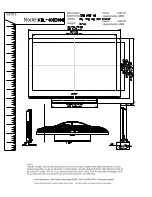
Page 12: ...8 Chapter 2 Hardware and Installation 2 1 Dimension and Outlines Product Dimension for HPC104GR HD1900B Series Measure Unit mm...

Page 13: ...9 Product Dimension for HPC150GR HD1900B Series Measure Unit mm...

Page 14: ...10 Product Dimension for HPC170GR HD1900B Series Measure Unit mm...

Page 15: ...11 Product Dimension for HPC 185SC HD1900B Series Measure Unit mm...

Page 16: ...3 Remove the screws on left and right side of the chassis cover as well to dissemble the chassis cover Notice When lifting the cover up to open the chassis for further installation see to it that the...

Page 17: ...the pins Diagram 2 1 illustrates how to set up a jumper 1 JP1 3 pin eDP Backlight VCC 5V 12V Select 1 1 2 Closed 5V Default 3 1 3 2 3 Closed 12V 2 JP2 4 pin eDP LCD VCC 3 3V 5V 12V Select 4 6 Closed...

Page 18: ...be displayed onscreen to inform you of this 5 AT_MODE 3 pin AT ATX Mode Function Select 1 1 3 3 AT_MODE ATX AT Mode Select 1 2 Close ATX Mode Selected Default 2 3 Close AT ModSelected ATX Mode Selecte...

Page 19: ...ult 2 3 Close VCC 9 JPCOM1 2 4 pin COM1 COM2 5V 12V Select 4 6 Closed 12V 3 4 Closed 5V 2 4 Closed RING Default 3 2 4 6 3 2 4 6 3 2 4 6 10 JPCOM3 4 4 pin COM3 COM4 5V 12V Select 4 6 Closed 12V 3 4 Clo...

Page 20: ...to the following instructions and illustration to install a 2 5 SATA HDD Before installation please refer to 2 2 to open the back cover and dissemble the pre installed HDD racks from the system 1 Alig...

Page 21: ...d M2 SATA Slot on the motherboard 2 Prepare compatible M 2 SATA Deferent type of cards has different length Find corresponding nut location for further installation 3 Remove the screw post and nut fix...

Page 22: ...ng instructions and illustration for the installation of the wireless LAN card 1 Locate the Mini PCIE card slot on the board Remove the marked screw and use it to lock WIFI card to the slot in later i...

Page 23: ...ntenna plugs from the Wi Fi antenna holes in the rear panel Connect the external Wi Fi receiver antenna to the antenna connector on the rear panel NOTE Please use an extended bracket when using a half...

Page 24: ...ength by adjusting the screw holes from both parts Make sure the screw holes from both parts matched and the USB cable fitted into the reserved slot of Part B as the photo shows 5 Turn over the system...

Page 25: ...s the entire hardware device and configures the parameters of the hardware synchronization Only when these tasks are completed done it gives up control of the computer to operating system OS Since the...

Page 26: ...o select screen Press up down to choose in the main menu the option you want to confirm or to modify Press Enter to select Press keys when you want to modify the BIOS parameters for the active option...

Page 27: ...figuration Security Password settings Boot To change boot settings Save Exit Save setting loading and exit options User can press the right or left arrow key on the keyboard to switch from menu bar Th...

Page 28: ...pear TPM State Use this item to enable or disable Security Device NOTE computer will reboot during restart in order to change state of the Device The optional settings Disabled Enabled ACPI Settings P...

Page 29: ...10 IO 2F0h IRQ 10 IO 2E0h IRQ 10 Serial Port FIFO Mode Use this item to select an optimal setting for FIFO Mode The optional settings are 16 Byte FIFO 32 Byte FIFO 64 Byte FIFO 128Byte FIFO OS Select...

Page 30: ...l exchange data Both computers should have the same or compatible settings Press Enter to make settings for the following items Terminal Type The optional settings VT100 VT100 VT UTF8 ANSI Emulation V...

Page 31: ...X XTERMR6 SCO ESCN VT400 Redirection After BIOS POST The settings specify if BootLoader is selected then Legacy console redirection is disabled before booting to Legacy OS Default value is Always Enab...

Page 32: ...hall appear CPUFAN Full Speed Temperature Use this item to set CPUFAN full speed temperature Fan will run at full speed when above the pre set temperature CPUFAN Full Speed Duty Use this item to set C...

Page 33: ...er The optional settings are Enabled Disabled When user set it as Enabled the following items will show up for user to make further settings SATA Speed Support The optional settings are Gen1 Gen2 SATA...

Page 34: ...m to enable or disable system wake up by RTC on alarm The optional settings Disabled Enabled When set as Enabled system will wake on the current time Increase minute s The range is from 1 to 60 minute...

Page 35: ...troller Auto uses default value for a root port it is 100 ms for a hub port the delay is taken from hub descriptor The optional settings Auto Manual Select Manual you can set value for the following s...

Page 36: ...280x1024 24 bit 2ch 1280x800 18 bit 1ch 1280x800 24 bit 1ch 1680x1050 24 bit 2ch 1280x768 24 bit 1ch 1920x1080 24 bit 2ch Note Please go back to Primary IGFX Boot Display for further setting The optio...

Page 37: ...ys On and former State are affected by ERP function Please disable ERP to support Always On and Former State The optional settings are Always Off Always On Former State 3 9 Security Menu Security menu...

Page 38: ...etup activation key Bootup Numlock State Use this item to select keyboard NumLock state The optional settings are On Off Quiet Boot The optional settings are Disabled Enabled Boot Option Priorities Bo...

Page 39: ...item to restore load default values for all the setup options Save as User Defaults Use this item to save the changes done so far as user defaults Restore User Defaults Use this item to restore defaul...

Page 40: ...Surface Hardness 3H ASTM D3363 pressure 750g 45 o Operating Force 80g Knock Test 10 000 000 times keystrokes HPC150GR HD1900B is designed based on the technology of 5 wire analog resistive type multi...

Page 41: ...y 80 3 Surface Hardness 3H ASTM D3363 pressure 750g 45 o Operating Force 80g Knock Test 10 000 000 times keystrokes HPC 185SC HD1900B is designed based on the technology projective capacitive type scr...

Page 42: ...Fi Alliance Usage Environment and Your Health Wireless LAN PCI Express Mini Card emits radio frequency electromagnetic energy like other radio devices However the level of energy emitted is far much l...

Page 43: ...imum exposure allowed by the Federal Communications Commission FCC This device complies with the limits for the Class B digital device pursuant to Part 15 subject to the following two conditions This...

Page 44: ...40...

Reviews: