background image

11

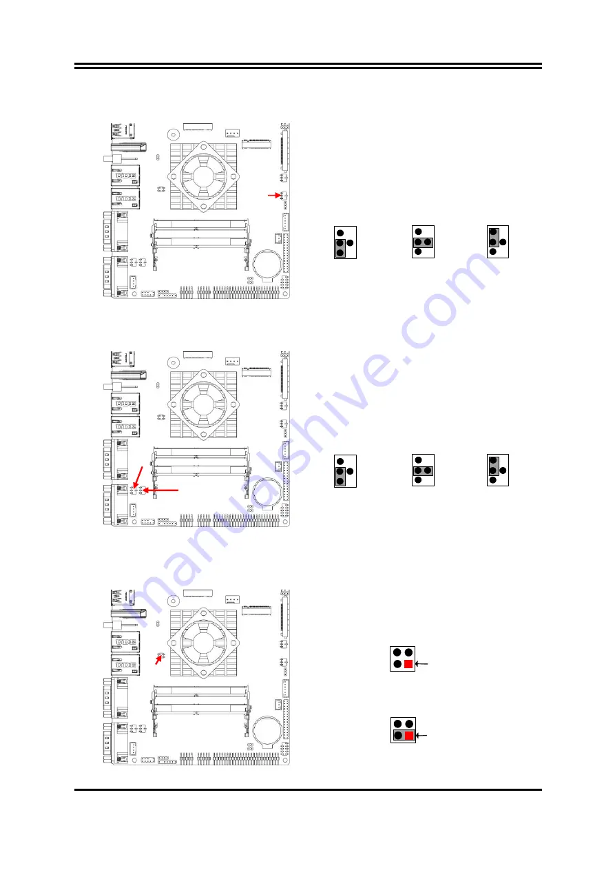
JPLCD (4-pin): LCD Panel VCC Select

(2.0 pitch)


JPLCD 

  LCD

 Panel VCC Select


2-4 Closed:   

VCC=+3.3V; 

3-4 Closed:     

VCC=+5V; 


4-6 Closed:     

VCC=+12V 

JPCOM1/2 (4-pin): COM1/COM2 Port Pin9 Function Select

(2.0 pitch)


JPCOM1 

  COM1 Port Pin-9 

JPCOM2 

  COM2 Port Pin-9 


2-4 Closed:   

PIN9=RS232; 

3-4 Closed:     

PIN9=+5V; 


4-6 Closed:     

PIN9=+12V   

Pin (1-2) of JBAT (4-pin): Clear ME_RTC

(2.0 pitch)


1-2 Closed: Clear ME_RTC 


1-2 Open: Normal(Default) 


PIN(1-2) Clear ME_RTC


Pin1 


Pin1 


JPCOM2

JPCOM1

JPLCD

JBAT

Summary of Contents for HPC150R-DCP1135G7 Series

Page 1: ...Panel PC User s Manual NO G03 PCLZ0FRFP F Manual Revision 1 0 Release Date 2022 03 03 ...

Page 2: ...er Settings 10 2 4 Hardware Installation 13 2 4 1 To Install SO DIMM to the Board 13 2 4 2 To Install M 2 M Key Card 14 2 4 3 To Install M 2 E Key Wi Fi Card 15 2 4 4 To Install M 2 B Key Card along with Nano SIM Card 18 2 4 5 To Install HDD 21 Chapter 3 Introducing BIOS 22 3 1 Entering Setup 21 3 2 BIOS Menu Screen 23 3 3 Function Keys 23 3 4 Getting Help 23 3 5 Menu Bars 24 3 6 Main Menu 24 3 7 ...

Page 3: ... Make sure to set up or use the product on a stable surface Make sure not to drop the product or strike it by any means Make sure not to move the product when the power is on Make sure not to step on the power cables and other cables or rest anything in them Be sure to ground yourself to prevent static charge when installing any internal components Use a grounding wrist strap and place all electro...

Page 4: ... any kind and will not be liable for any indirect special incidental or consequential damages including damages for loss of profit loss of business loss of use of data interruption of business and the like Products and corporate names appearing in this manual may or may not be registered trademarks or copyrights of their respective companies and they are used only for identification or explanation...

Page 5: ...vice expansion 1 M 2 M key 2242 2280 PCIe 4 0 x4interface supports NVMe 1 M 2 E key 2230 USB2 0 PCIex1 interface supports CNVi 1 M 2 B key 3042 3052 6570 supports 3G 4G 5G Module 1 SIM card slot 2 Intel GbE 2 USB3 2 Gen2 4 USB2 0 Support 2 RS232 422 485 2 RS232 Support CPU Smart FAN Compliance with ErP standard Support Watchdog function The system has the following features besides other basic fun...

Page 6: ...ezel Display Type 15 0 with LED Backlight Brightness cd m 350 nits Display Color 16 7m display color Resolution 1024 x 768 60Hz Viewing Angle 178 178 H V Pixel Pitch 0 099 x 0 297mm Aspect Ratio 4 3 Contrast Ratio 1000 1 Response Time 35 ms Touch Screen Type 5 wires analog resistive type Active Range 346 0 x 270 0mm 0 3mm Transparency 80 3 Operating force 100g Surface Hardness 3H pressure 750g 45 ...

Page 7: ...45 LAN 1 Intel I225V 2 5G 1 Intel I219LM GbE 1 12 36V DC in Locking Jack 1 Power button 1 2pin Front Power button Power Power Input 12 36V DC in AC version 100 240V AC DC 60W power adapter or DC version 12VDC with over current protection fuse Power Consumption 45W Dimensions Case Dimensions 378 00 294 00 60 00mm Certification Compliance Certifications CE FCC IP65 Front Environment Temperature Oper...

Page 8: ...e system Power Button Jack For user to turn on off the system AT ATX Mode Switch AT ATX mode Supported at front side I O switch AT Directly PWR on as Power input ready ATX Press Button to PWR on after Power input ready Note User can switch up for ATX Mode or switch down for AT Mode USB 3 2 Ports To connect USB keyboard mouse or other devices compatible with USB3 2 specification USB 3 2 Gen 2 ports...

Page 9: ...nnector Description DCIN1 3 pin 12 36V DC in Power Connector Pin No Definition 1 12 36V VCC 2 GND 3 GND Warning Find Pin 1 position before connecting power cable to this 3 pin power connector WRONG INSTALLATION DIRECTION WILL DAMAGE THE BOARD FPW_SW 2 pin block Power button jack RJ 45 Ethernet Connector There are two LED next to the LAN port Please refer to the table below for the LAN port LED ind...

Page 10: ... NC NC 7 RTS NC NC 8 CTS NC NC 9 RI NC NC COM1 COM2 ports can function as RS232 422 485 port In normal settings COM1 COM2 functions as RS232 port With compatible COM cable they can function as RS422 or RS 485 port User also needs to go to BIOS to set Transmission Mode Select for Serial Port 1 Configuration or Serial Port 2 Configuration refer to Page 28 at first before using specialized cable to c...

Page 11: ...back shell refer to 2 4 3 step 1 to make further settings on the daughter board for specific function User can set COM3 4 as GPIO port by setting up JP2 JP18 Pin 2 3 closed The pin assignment for GPIO connector is listed as follows For GPIO VCC please refer to jumper JP1 from the daughter board for further settings JP2 JP18 JP1 ...

Page 12: ...8 Chapter 2 Hardware and Installation 2 1 Dimension and Outlines Measure Unit mm ...

Page 13: ...m upon a stable platform with this side up Tighten up the screws in the marked spots to remove HDD and SO DIMM covers 2 User can install expansion parts according to their own needs DDR4 SO DIMMs M 2 M key type 2242 2280 card M 2 E key type 2230 card M 2 B key type 3042 3052 6570 card along with compatible Nano SIM card and compatible 2 5 hard disk HDD Cover DDR4 SO DIMM Cover ...

Page 14: ...move jumper clip from 2 jumper pins to open the pins Diagram 2 1 illustrates how to set up a jumper JP1 3 pin EDP BACKLIGHT VCC Select 2 0 pitch JP2 4 pin EPD Panel VCC Select 2 0 pitch JP2 EDP Panel VCC Select 2 4 Closed VCC 3 3V 3 4 Closed VCC 5V 4 6 Closed VCC 12V 1 3 5 4 6 2 6 4 2 5 3 1 4 6 2 5 3 1 JPLED 3 pin LCD BACKLIGHT VCC Select 2 0 pitch JPLED ...

Page 15: ...1 JPCOM1 2 4 pin COM1 COM2 Port Pin9 Function Select 2 0 pitch JPCOM1 COM1 Port Pin 9 JPCOM2 COM2 Port Pin 9 2 4 Closed PIN9 RS232 3 4 Closed PIN9 5V 4 6 Closed PIN9 12V 1 3 5 4 6 2 6 4 2 5 3 1 4 6 2 5 3 1 Pin 1 2 of JBAT 4 pin Clear ME_RTC 2 0 pitch 1 2 Closed Clear ME_RTC 1 2 Open Normal Default PIN 1 2 Clear ME_RTC Pin1 2 Pin1 2 3 4 4 3 JPCOM2 JPCOM1 JPLCD JBAT ...

Page 16: ... JBAT 4 pin Clear CMOS Setting 2 0 pitch 3 4 Closed Clear CMOS 3 4 Open Normal Default PIN 3 4 Clear CMOS Pin1 2 Pin1 2 3 4 4 3 J80PORT 2 pin GPIO Select 2 0 pitch 1 2 Closed GPIO 1 2 Open 80 port Pin1 2 Pin1 2 JBAT ...

Page 17: ... gold figure side of a compatible SO DIMM into the slot at a 30 degree See to it that the break of the module fit into the notch of the slot and the golden finger side should be fully plugged into the slot 3 Press down to secure the SO DIMM to the slot The eject tabs will lock automatically if installing direction is correct ...

Page 18: ... compatible M 2 M key type 2242 card into the slot 4 Lock the card to the board by tightening up the screw to the marked spot Note the screw post and nut fixed at location MH2 by default for 4 2cm type 2242 card installation If you wish to install type 2280 card please remove corresponding screw post under the screw as well and lock the screw post into location MH4 before installing 8 cm type 2280...

Page 19: ...rresponding metal button on the installed WiFi card so they need to remove the whole chassis heat sink shell on the back of the Panel PC for further installation which is different from 2 2 please refer to the following steps for the installation of the compatibale M 2 E Key Wi Fi card 1 Remove the screws in the marked red circle spots and dissemble the whole chassis heat sink shell from the Panel...

Page 20: ...ear off the acetate tape which protects the metal hats of the string end Notice The other wires cables must be wrapped with Insulated Tape and placed in the original position to avoid short circuit caused by contact between the metal parts and the mainboard 3 Locate M 2 E key slot on the board 4 Remove the screw post screw nut in the marked spot MH1 ...

Page 21: ...al hats of Wi Fi antenna strings Press the metal hats of the antenna string end to the antenna slots on the card as showed 8 Locate the Wi Fi antenna holes of the IO panel Connect the external Wi Fi receiver antenna to the antenna head on the panel Note We suggest that the connection of the external Wi Fi receiver antenna be made after all hardware installation finished and the chassis is assemble...

Page 22: ... 3G 4G 5G module co function with SIM card installed 1 to install compatible SIM card into SIM card slot 1 Locate SIM card slot on the board 2 Use a pair of tweezers to pick up compatible SIM card and push it into the slot in the direction as shown 3 The board with compatible SIM card installed in place ...

Page 23: ...s in different lengths The installation steps are basically the same Take the installation process of type 3052 card as an example 1 Locate M 2 B key slot on the board 2 Remove the screw nut in the marked spot MH2 for further installation Type 3042 MH1 Type 3052 MH2 Type 6570 MH3 MH4 ...

Page 24: ...ly emerged into the slot and then secure it by tightening the screws at locations MH3 MH4 Note In the case that compatible M2B card comes with metal buttons to be connected with antenna strings user needs to dissemble the whole heat sink on the back of the Panel PC and pick out the antenna string from hidden cable buddle please refer to 2 4 3 The installation steps for M2E card and M2B card are ba...

Page 25: ...d HDD space Please refer to the following instructions and illustration to install a 2 5 SATA HDD Before installation 1 Locate the HDD connector onboard and prepare compatible 2 5 SATA hard disk 2 Insert compatible HDD into HDD connector in the direction shown 3 Install HDD cover back to the chassis after all necessary installation finished ...

Page 26: ...dware device and configures the parameters of the hardware synchronization Only when these tasks are completed done it gives up control of the computer to operating system OS Since the BIOS is the only channel for hardware and software to communicate it is the key factor for system stability and in ensuring that your system performance as its best 3 1 Entering Setup Power on the computer and by pr...

Page 27: ...o modify Press Enter to select Press keys when you want to modify the BIOS parameters for the active option F1 General help F2 Previous values F3 Optimized defaults F4 Save Exit Press Esc to exit from BIOS Setup 3 4 Getting Help Main Menu The on line description of the highlighted setup function is displayed at the top right corner the screen Status Page Setup Menu Option Page Setup Menu Press F1 ...

Page 28: ...tting loading and exit options User can press the right or left arrow key on the keyboard to switch from menu bar The selected one is highlighted 3 6 Main Menu Main menu screen includes some basic system information Highlight the item and then use the or and numerical keyboard keys to select the value you want in each item System Date Set the date Please use Tab to switch between data elements Sys...

Page 29: ...sub items Intel VMX Virtualization The optional settings are Disabled Enabled When set as Enabled a VMM can utilize the additional hardware capabilities provided by Vanderpool Technology Intel R SpeedStep tm This item allows more than two frequency ranges to be supported The optional settings are Disabled Enabled C states Use this item to enable or disable CPU Power Management Allows CPU to go to ...

Page 30: ...Note In the case that user needs to update Me firmware user should set Me FW Image Re Flash as Enabled save the settings and exit The system will turn off and reboot after 4 seconds If the user goes to BIOS screen again will find this item is set again as Disabled but user can still re flash to update firmware next time Trusted Computing Press Enter to view current status information or make furth...

Page 31: ...isabled Enabled Note This function is supported when ERP Support is set as Disabled USB S5 Power Use this item to enable or disable USB Power after System Shutdown The optional settings Disabled Enabled Note This function is supported when ERP Support is set as Disabled Super IO Configuration Press Enter to make settings for the following sub items uper IO Configuration ERP Support Use this item t...

Page 32: ...ode Speed Select Use this item to select RS232 RS422 RS485 Speed The optional settings RS232 RS422 RS485 250Kbps RS232 1Mbps RS422 RS485 10Mbps Serial Port 3 Configuration Press Enter to make settings for the following items Serial Port 3 Configuration Serial Port Use this item to enable or disable Serial Port COM The optional settings Disabled Enabled When set as Enabled user can make further set...

Page 33: ...to 255 minutes when WatchDog Reset Timer Unit set as Min WatchDog Reset Timer Unit The optional settings Sec Min Case Open Detect Use this item to detect case has already open or not show message in POST The optional settings Disabled Enabled When set as Enabled system will detect if COPEN has been short or not refer to CASE jumper setting for Case Open Detection if Pin 1 2 of CASE are short syste...

Page 34: ...Port Console Redirection COM1 Console Redirection Use this item to enable or disable COM1 Console Redirection The optional settings Disabled Enabled When set as Enabled user can make further settings in the following items Console Redirection Settings The settings specify how the host computer and the remote computer which the user is using will exchange data Both computers should have the same or...

Page 35: ...its indicate the end of a serial data packet A start bit indicates the beginning The standard setting is 1 stop bit Communication with slow devices may require more than 1 stop bit The optional settings 1 2 Flow Control Flow control can prevent data loss from buffer overflow When sending data if the receiving buffers are full a stop signal can be sent to stop the data flow Once the buffers are emp...

Page 36: ...in Console Redirection Settings page for more help with Terminal Type Emulation Bits per second EMS Use this item to select serial port transmission speed The speed must be matched on the other side Long or noisy lines may require lower speeds The optional settings 9600 19200 57600 115200 Flow Control EMS Flow control can prevent data loss from buffer overflow When sending data if the receiving bu...

Page 37: ...rements Network Stack Configuration Press Enter to go to Network Stack screen to make further settings Network Stack Use this item to enable or disable UEFI Network Stack The optional settings Disabled Enabled When set as Enabled the following sub items shall appear IPv4 PXE Support Use this item to enable IPv4 PXE boot support When set as Disabled IPv4 boot support will not be available The optio...

Page 38: ...480 18bit Single 800x600 18bit Single 800x600 24bit Single 1024x600 18bit Single 1024x768 18bit Single 1024x768 24bit Single 1280x768 24bit Single 1280x800 18bit Single 1280x800 24bit Single 1366x768 18bit Single 1366x768 24bit Single 1440x900 18bit Dual 1440x900 24bit Dual 1280x1024 24bit Dual 1680x1050 24bit Dual 1920x1080 24bit Dual LVDS FW Write Protect Use this item to support LVDS FW update ...

Page 39: ...bled Enabled Disabled HDA will be unconditionally disabled Enabled HAD will be unconditionally enabled System State After Power Failure Use this item to specify what state to go to when power is re applied after a power failure G3 state The optional settings Always On Always Off Former State Note The option Always On and Former State are affected by ERP Support function Please disable ERP to suppo...

Page 40: ...he new administrator password Secure Boot Press Enter to make customized secure settings System Mode Secure Boot Secure Boot feature is active if secure boot is enabled Platform Key PK is enrolled and the system is in user mode The mode change requires platform reset The optional settings are Disabled Enabled Secure Boot Mode Use this item to Secure Boot mode to Standard mode or Custom mode This c...

Page 41: ... image to run in Secure Boot mode Enroll SHA256 Hash certificate of a PE image into Authorized Signature Database db Device Guard Ready Remove UEFI CA from DB Restore DB default This item restore DB variable to factory defaults Secure Boot variable Size Keys Key Source Platform Key PK Key Exchange Keys Authorized Signatures Forbidden Signatures Authorized TimeStamps OsRecovery Signatures Use this ...

Page 42: ...sabled Enabled Boot Option Priorities 3 11 Save Exit Menu Save Options Save Changes and Reset This item allows user to reset the system after saving the changes Discard Changes and Reset This item allows user to reset the system without saving any changes Default Options Restore Defaults Use this item to restore load default values for all the setup options Save as User Defaults Use this item to s...

Page 43: ... Fi Alliance Usage Environment and Your Health Wireless LAN PCI Express Mini Card emits radio frequency electromagnetic energy like other radio devices However the level of energy emitted is far much less than the electromagnetic energy emitted by wireless devices like for example mobile phones Due to the fact that Wireless LAN PCI Express Mini Card operates within the guidelines found in radio fr...

Page 44: ...ximum exposure allowed by the Federal Communications Commission FCC This device complies with the limits for the Class B digital device pursuant to Part 15 subject to the following two conditions This device may not cause harmful interference This device must accept any interference received including interference that may cause undesired operation The FCC limits are designed to provide reasonable...

Reviews: