background image


32 

Modem Use IRQ 

This determines the IRQ in which the MODEM can use. 
The settings are: 3, 4, 5, 7, 9, 10, 11, NA. 

Power Button Function 

Pressing the power button for more than 4 seconds forces the system to enter the Soft-Off state.  
The settings are: Delay 4 Sec, Instant-Off. 

State After Power Failure 

This item allows the system power ON/OFF automatic when power loss and recovery again, 
you can choose Auto for recovery pre-state, or always ON/OFF after power recovery.  

Wake Up Events 

Please refer to section 3-8-1 
 

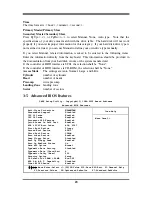
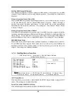
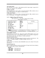
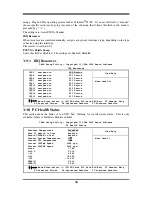
3-8-1   Wake up Events 

CMOS Setup Utility – Copyright(C) 1984-2002 Award Software 

Wake Up Events 


Item Help 


    VGA                             OFF  
    LPT & COM                       LPT/COM 
    HDD & FDD                       ON 
    PCI Master                      OFF 
    Wake-Up on Ring                 Disabled 
    Wake-Up on PCI PME              Disabled 
    PS2 KB Wakeup Selection         Hot Key 
    Wake-Up On Hot Key (PS2 KB)     Disabled 
    Wake-Up on RTC Alarm            Disabled  
  x Date of Month Alarm              0 
  x Time (hh:mm:ss) Alarm            0 : 0 : 0    
  > IRQs Activities                 Press Enter 


  Menu Level >> 
 

↑↓→←

 Move Enter:/-/PU/PD:Value F10:Save ESC:Exit  F1:General Help 

F5:Previous Values    F6:Optimized Defaults   F7:Standard Defaults 

Wake Up On Ring/PME 

During Disabled, the system will ignore any incoming call from the modem. During 
Enabled, the system will boot up if there’s an incoming call from the modem. 

Wake-Up on RTC Alarm 

This function is for setting date and time for your computer to boot up.  During Disabled, 
you cannot use this function.  During Enabled, choose the Date and Time Alarm: 

Date(of month) Alarm 

You can choose which month the system will boot up.  Set to 0, to boot every day. 

Time(hh:mm:ss) Alarm  

You can choose what hour, minute and second the system will boot up. 

Note:

  If you have change the setting, you must let the system boot up until it goes to 

the operating system, before this function will work. 

IRQs Activities 

Please refer to section 3-8-1.1 

Summary of Contents for V333U

Page 1: ...O G03 V333UR1A Release date July 2002 Trademark Specifications and Information contained in this documentation are furnished for information use only and are subject to change at any time without notice and should not be construed as a commitment by manufacturer ...

Page 2: ...CEDURE FOR EXPANSION CARD INSTALLATION 12 2 5 2 ASSIGNING IRQ FOR EXPANSION CARD 12 2 5 3 INTERRUPT REQUEST TABLE FOR THIS MOTHERBOARD 13 2 5 4 AGP SLOT 13 2 6 CONNECTORS HEADERS 13 2 6 1 CONNECTORS 13 2 6 2 HEADERS 16 2 7 STARTING UP YOUR COMPUTER 19 CHAPTER 3 INTRODUCING BIOS 3 1 ENTERING SETUP 20 3 2 GETTING HELP 20 3 3 THE MAIN MENU 21 3 4 STANDARD CMOS FEATURES 22 3 5 ADVANCED BIOS FEATURES 2...

Page 3: ...ATE BIOS 45 USER S NOTICE COPYRIGHT OF THIS MANUAL BELONGS TO THE MANUFACTURER NO PART OF THIS MANUAL INCLUDING THE PRODUCTS AND SOFTWARE DESCRIBED IN IT MAY BE REPRODUCED TRANSMITTED OR TRANSLATED INTO ANY LANGUAGE IN ANY FORM OR BY ANY MEANS WITHOUT WRITTEN PERMISSION OF THE MANUFACTURER THIS MANUAL CONTAINS ALL INFORMATION REQUIRED TO USE V333U MOTHER BOARD AND WE DO ASSURE THIS MANUAL MEETS US...

Page 4: ...roved processor heat dissipation through increased surface area and concentrated airflow from attached fans In addition interface materials allow effective transfers of heat from the processor to the heatsink For optimum heat transfer AMD recommends the use of thermal grease and mounting clips to attach the heatsink to the processor When selecting a thermal solution for your system please refer to...

Page 5: ... Surround Effect For those wanting even greater graphic performance an AGP 4X slot is included on the board With USB control as well as capability of expanding to 6 USB function ports support USB2 0 USB1 1 Devices the V333U meet future USB demand also this motherboard has built in hardware monitor function This will monitor and protect your computer A special design in hardware for protecting Athl...

Page 6: ... Expandable to 3 0GB Expansion Slot Headers AGP slot x1 support AGP 2 0 4X mode 32 bit PCI slot x5 CNR slot x1 Integrate IDE Two PCI IDE controllers support PCI Bus Mastering ATA PIO DMA and the ULTRA DMA 33 66 100 133 functions that deliver the data transfer rate up to 133 MB s Audio AC 97 Digital Audio controller integrated AC 97 Audio CODEC on board Audio driver and utility included Support 4 c...

Page 7: ...3D Mark 2000 5678 5687 3D Mark 2001 2554 2550 3D Winbench 2000 105 105 Final Reality 10 34 10 39 Content Creation Winstone 2000 50 50 3 Content Creation Winstone 2001 63 6 64 5 Content Creation Winstone 2002 23 6 23 9 Business Winstone2001 53 9 53 7 Winbench 99 CPU Mark 99 152 151 FPU Winmark 99 9140 9140 Business Disk Winmark99 7440 7690 Hi end Disk Winmark99 19600 19400 Business Graphic Winmark ...

Page 8: ...HF Chip IR Connector CNR Slot Front Panel Audio PC99 Back Panel CD Audio PCI Slot AGP Slot K B Power ON Jumper JP1 FAN2 Floppy Connector VIA KT333 Chip Front Panel Connector ATA 133 IDE Connector Clear CMOS JBAT ATX Power Connector CPU FAN 2MBit Flash ROM BIOS JP6 CPU Ratio Selector CPU Socket DDR Socket X3 VIA VT8235 Chip Wake On LAN FAN1 CPU Front Side Bus Frequency Jumper JP4 PS2 KB Mouse Port ...

Page 9: ...ector 40 pin Block P 15 Headers Header Name Description Page AUDIO Line In Out MIC header 9 pin Block P 16 USB1 USB2 USB Port Headers 9 pin Block P 16 IDE LED IDE activity LED 2 pin Block P 16 TB LED Turbo LED switch 2 pin Block P 16 RESET Reset switch lead 2 pin Block P 17 SPEAKER Speaker connector 4 pin Block P 17 PWR LED Power LED 2 pin Block P 17 PW BN Power switch 2 pin Block P 17 WOL Wake On...

Page 10: ...river utility 2 2 Checking Motherboard s Jumper Setting 1 CPU Ratio Selector 10 pin JP6 Ratio 1 2 3 4 5 Ratio 1 2 3 4 5 5 0x ON ON ON OFF ON 9 0x ON ON ON OFF OFF 5 5x ON OFF ON OFF ON 9 5x ON OFF ON OFF OFF 6 0x ON ON OFF OFF ON 10 0x ON ON OFF OFF OFF 6 5x ON OFF OFF OFF ON 10 5x ON OFF OFF OFF OFF 7 0X ON ON ON ON OFF 11 0x ON ON ON ON ON 7 5x ON OFF ON ON OFF 11 5x ON OFF ON ON ON 8 0x ON ON O...

Page 11: ...the CMOS data To clear the CMOS follow the procedure below 1 Turn off the system and unplug the AC power 2 Remove ATX power cable from ATX power connector 3 Locate JBAT and short pins 2 3 for a few seconds 4 Return JBAT to its normal setting by shorting pins 1 2 5 Connect ATX power cable back to ATX power connector Note When should clear CMOS 1 Troubleshooting 2 Forget password 3 After over clocki...

Page 12: ...r mouse and external modems Parallel Port a low speed interface typically used for printers PS 2 a low speed interface used for mouse and keyboards USB Universal Serial Bus a medium speed interface typically used for mouse keyboards scanners and some digital cameras Sound interface the interface between the sound card or integrated sound connectors and speakers MIC game controllers and MIDI sound ...

Page 13: ...and motherboard Over heat Protect Only for Athlon XP serial CPU when the CPU overheat system will auto shut down power supply You can hear a continue beep sound the power button will be locked up Users must turn off and turn on the AC power to reset the system otherwise the power button will no function the other way is keeping press the push button few seconds till the beep sound stop then releas...

Page 14: ... system may hang during startup Generally installing DDR SDRAM modules to your motherboard is very easy you can refer to figure 2 4 to see what a 184 Pin PC1600 PC2100 PC2700 DDR SDRAM module looks like DDR2 BANK2 BANK3 DDR1 BANK0 BANK1 DDR3 BANK4 BANK5 NOTE When you install DIMM module fully into the DIMM socket the eject tab should be locked into the DIMM module very firmly and fit into its inde...

Page 15: ...7 Install the necessary software driver for your expansion card 2 5 2 Assigning IRQs For Expansion Card Some expansion cards need an IRQ to operate Generally an IRQ must exclusively assign to one use In a standard design there are 16 IRQs available but most of them are already in use Standard Interrupt Assignments IRQ Priority Standard function 0 N A System Timer 1 N A Keyboard Controller 2 N A Pr...

Page 16: ...ake the system unstable or cards inoperable 2 5 4 AGP Slot This motherboard provides an AGP Slot support the 1X 2X 4X AGP VGA card AGP SLOT 2 6 Connectors Headers 2 6 1 Connectors 1 Power Connector 20 pin block ATXPOW ATX Power Supply connector This is a new defined 20 pins connector that usually comes with ATX case The ATX Power Supply allows to use soft power on momentary switch that connect fro...

Page 17: ...udio and Game Connector AUD_GAME This Connector are 3 phone Jack for LINE OUT LINE IN MIC and a 15 pin D Subminiature Receptacle Connector for joystick MIDI Device Line out Audio output to speaker Line in Audio input to sound chip MIC Microphone Connector Game MIDI For joystick or MIDI Device 6 Serial Port COM1 COM2 COM1 COM2 COM1 COM2 are the 9 pin D Subminiature mail connector The On board seria...

Page 18: ... by setting its jumpers accordingly Please refer to the documentation of your hard disk for the jumper settings Primary IDE Connector Pin 1 IDE1 9 Secondary IDE Connector 40 pin block IDE2 This connector connects to the next set of Master and Slave hard disks Follow the same procedure described for the primary IDE connector You may also configure two hard disks to be both Masters using one ribbon ...

Page 19: ... MIC L IN R L OUT R GND GND MICP 2 USB Port Headers 9 pin USB1 USB2 These headers are used for connecting the additional USB port plug By attaching an option USB cable your can be provided with two additional USB plugs affixed to the back panel USB Port Connector Pin 1 USB1 VCC DATA GND DATA VCC GND DATA GND DATA Pin 1 USB2 VCC DATA GND DATA VCC GND DATA GND DATA 3 IDE Activity LED IDE LED This co...

Page 20: ...s light on while the system power is on Connect the Power LED from the system case to this pin 8 Power switch PW BN This 2 pin connector connects to the case mounted power switch to power ON OFF the system System Case Connections GND Turbo LED GND Reset SW VCC GND Turbo SW Speaker VCC NC GND Power LED NC GND VCC IDELED PW BN 9 Wake On LAN Headers 3 pin WOL This connector connects to a LAN card wit...

Page 21: ...UFAN 1 3 FAN1 1 3 FAN2 1 3 11 IR infrared module Headers 9 pin IR This connector supports the optional wireless transmitting and receiving infrared module You must configure the setting through the BIOS setup to use the IR function IRRX GND IRTX VCC Infrared Module Headers IR CIR CIRRX IOVSB NC NC NC CIR Pin6 Pin10 for Consumer IR IR Pin1 Pin5 for Standard IR 6 1 10 5 12 CD Audio In Headers 4 pin ...

Page 22: ...e system will then run power on test While the test are running the BIOS will alarm beeps or additional message will appear on the screen If you do not see any thing within 30 seconds from the time you turn on the power The system may have failed on power on test Recheck your jumper settings and connections or call your retailer for assistance Beep Meaning One short beep when displaying logo No er...

Page 23: ...ight to choose in the main menu the option you want to confirm or to modify Press F10 when you have completed the setup of BIOS parameters to save these parameters and to exit the BIOS Setup menu Press Page Up Page Down or keys when you want to modify the BIOS parameters for the active option 3 1 Entering Setup Power on the computer and by pressing Del immediately allows you to enter Setup If the ...

Page 24: ...t User Password Save Exit Setup Exit Without Saving Esc Quit Select Item F10 Save Exit Setup Time Date Hard Disk Type Figure 3 1 Standard CMOS Features Use this Menu for basic system configurations Advanced BIOS Features Use this menu to set the Advanced Features available on your system Advanced Chipset Features Use this menu to change the values in the chipset registers and optimize your system ...

Page 25: ...n keys to select the value you want in each item CMOS Setup Utility Copyright C 1984 2002 Award Software Standard CMOS Features Item Help Date mm dd yy Wed Jul 03 2002 Time hh mm ss 16 45 35 IDE Primary Master Press Enter None IDE Primary Slave Press Enter None IDE Secondary Master Press Enter None IDE Secondary Slave Press Enter None Drive A 1 44M 3 25 in Drive B None Video EGA VGA Halt On All Bu...

Page 26: ... Access Mode The settings are Auto Normal Large and LBA Cylinder number of cylinders Head number of heads Precomp write precomp Landing Zone landing zone Sector number of sectors 3 5 Advanced BIOS Features CMOS Setup Utility Copyright C 1984 2002 Award Software Advanced BIOS Features Item Help Anti Virus Protection Disabled PhoneixNet Support Disabled CPU L1 Cache Enabled CPU L2 Cache Enabled Proc...

Page 27: ... AMD Athlon XP SSE Feature Quick Power On Self Test This category speeds up Power On Self Test POST after you power on the computer If this is set to Enabled BIOS will shorten or skip some check items during POST Enabled default Enable quick POST Disabled Normal POST First Second Third Fourth Boot Device The BIOS attempts to load the operating system from the devices in the sequence selected in th...

Page 28: ...tered at the prompt Setup default The system will boot but access to Setup will be denied if the correct password is not entered prompt OS Select For DRAM 64MB Allows OS2 to be used with 64MB or DRAM Settings are Non OS 2 default and OS2 Set to OS 2 if using more than 64MB and running OS 2 3 6 Advanced Chipset Features The Advanced Chipset Features Setup option is used to change the values of the ...

Page 29: ...eserved it cannot be cached The user information of peripherals that need to use this area of system memory usually discusses their memory requirements The settings are Enabled and Disabled 3 6 1 DRAM Timing Settings CMOS Setup Utility Copyright C 1984 2002 Award Software DRAM Timing Settings Item Help Auto Configuration Optimized RAS Active Time 6T RAS Precharge Time 3T RAS to CAS Delay 3T CAS La...

Page 30: ...sabled AGP Master 1 WS Write Enabled AGP Master 1 WS Read Enabled CPU to AGP Post Write Disabled AGP Delay Transaction Disabled Menu Level Move Enter Select PU PD Value F10 Save ESC Exit F1 General Help F5 Previous Values F6 Optimized Defaults F7 Standard Defaults Note Change these settings only if you are familiar with the chipset 3 6 3 PCI Timing Settings CMOS Setup Utility Copyright C 1984 2002...

Page 31: ...7 3 Init Display First This item allows you to decide to activate whether PCI Slot or AGP VGA first The settings are PCI Slot AGP Slot 3 7 1 OnChip IDE Function CMOS Setup Utility Copyright C 1984 2002 Award Software OnChip IDE Function Item Help OnChip IDE Channel0 Enabled OnChip IDE Channel1 Enabled Primary Master PIO Auto Primary Slave PIO Auto Secondary Master PIO Auto Secondary Slave PIO Auto...

Page 32: ... 33 and Ultra DMA 66 select Auto to enable BIOS support The settings are Auto Disabled IDE HDD Block Mode Block mode is also called block transfer multiple commands or multiple sector read write If your IDE hard drive supports block mode most new drives do select Enabled for automatic detection of the optimal number of block read writes per sector the drive can support The settings are Enabled Dis...

Page 33: ...e SPP EPP Mode Select EPP1 9 ECP Mode Use DMA 3 Menu Level Move Enter Select PU PD Value F10 Save ESC Exit F1 General Help F5 Previous Values F6 Optimized Defaults F7 Standard Defaults Onboard FDD Controller Select Enabled if your system has a floppy disk controller FDD installed on the system board and you wish to use it If you install add on FDC or the system has no floppy drive select Disabled ...

Page 34: ...Setup allows you to configure your system to most effectively save energy saving while operating in a manner consistent with your own style of computer use CMOS Setup Utility Copyright C 1984 2002 Award Software Power Management Setup Item Help ACPI Function Enabled Video Off Option Suspend off Video off Method V H SYNC Blank MODEM Use IRQ 3 Power Button Function Instant Off State After Power Fail...

Page 35: ...Wake Up on RTC Alarm Disabled x Date of Month Alarm 0 x Time hh mm ss Alarm 0 0 0 IRQs Activities Press Enter Menu Level Move Enter Select PU PD Value F10 Save ESC Exit F1 General Help F5 Previous Values F6 Optimized Defaults F7 Standard Defaults Wake Up On Ring PME During Disabled the system will ignore any incoming call from the modem During Enabled the system will boot up if there s an incoming...

Page 36: ...tems and it is strongly recommended that only experienced users should make any changes to the default settings CMOS Setup Utility Copyright C 1984 2002 Award Software PnP PCI Configurations Item Help PnP OS Installed No Reset Configuration Data Disabled Resources Controlled By Manual x IRQ Resources Press Enter PCI VGA Palette Snoop Disabled Assign IRQ For VGA Enabled Assign IRQ For USB Enabled M...

Page 37: ...signed to PCI Device IRQ11 assigned to PCI Device IRQ12 assigned to PCI Device IRQ14 assigned to PCI Device IRQ15 assigned to PCI Device Menu Level Move Enter Select PU PD Value F10 Save ESC Exit F1 General Help F5 Previous Values F6 Optimized Defaults F7 Standard Defaults 3 10 PC Health Status This section shows the Status of you CPU Fan Warning for overall system status This is only available if...

Page 38: ...Boot is CPU Vcore Select Default AGP VddQ Select 1 5V Default VDIMM Select 2 5V Default Menu Level Move Enter Select PU PD Value F10 Save ESC Exit F1 General Help F5 Previous Values F6 Optimized Defaults F7 Standard Defaults Auto Detect DIMM PCI Clk This item allows you to enable disable auto detect DIMM PCI Clock Spread Spectrum This item allows you to set the CPU Host PCI clock and Spread Spectr...

Page 39: ...acters in length and press Enter The password typed now will clear any previously entered password from CMOS memory You will be asked to confirm the password Type the password again and press Enter You may also press Esc to abort the selection and not enter a password To disable a password just press Enter when you are prompted to enter the password A message will confirm that the password will be...

Page 40: ...L Menu should appear as below If the menu does not appear double click MY COMPUTER double click CD ROM drive or click START click RUN type X SETUP EXE assuming X is your CD ROM drive From MAGIC INSTALL MENU you may make 9 selections 1 VIA 4 IN 1 install VIA Service Pack 4 IN 1 driver 2 SOUND install AC97 Audio Codec Installing driver 3 PC HEALTH install Winbond PC HEALTH hardware monitor Software ...

Page 41: ...DRIVER AND INTERFACE DIRECTLY TO HARDWARE PROVIDING FAST GRAPHIC ACCESS IRQ ROUTING VIA PCI IRQ MINIPORT DRIVER IS TO BE INSTALLED UNDER WIN98 ONLY IT WILL FIX PCI IRQ ROUTING SEQUENCE INF VIA REGISTRY DRIVER IS TO BE INSTALLED UNDER WINDOWS THE DRIVER WILL ENABLE VIA POWER MANAGERMENT CONTROLLER 1 Click IDE when MAGIC INSTALL MENU appears 2 Click NEXT when VIA Service Pack Wizard appears 3 This i...

Page 42: ...ed DMA Mode 7 Click NEXT to Install VIA AGP VXD Driver 8 Click NEXT to Install VIA IRQ Routing Mini port Driver 9 Click Finish to restart computer 4 2 SOUND Install CMI Audio Codec Driver 1 Click SOUND when MAGIC INSTALL MENU appears 2 Choose Install component in Installation Package ...

Page 43: ...onent and Click Next 6 Click Next when Start copying files windows appears OS can Auto Find C Media AC97 Audio Device Click Next 7 C Media Media Rack Play table 8 C Media Audio Configuration setting 9 C Media Multi Channel Audio Demo Program you can Test speaker position 10 When Enabled XeaR you can plug earphone in Speak Out connector as a Rear speaker and 2 channel speaker plug in Line In as Fro...

Page 44: ...ck the Button to start installation 4 Select Program Group name or enter a new group name click continue to setup and click OK after setup complete 4 3 1 How To Utilize PC HEALTH 1 Click Program Winbond Hardware Doctor Hardware Doctor the Winbond Hardware Doctor will appears You can remove the Utility in Control Panel Add Remove Program icon 2 After executing Winbond Hardware Doctor it supports sy...

Page 45: ...con you will have this picture choose from internet you can upgrade BIOS On line 5 When On line update BIOS the program will auto check your BIOS version 6 Click Next if you need update BIOS after upgrade BIOS the system will clear CMOS and automatically restart 7 Click Yes if you want to update the BIOS otherwise choose No to exit 8 When System programming BIOS don t turn off power after finish u...

Page 46: ... PC CILLIN when MAGIC INSTALL MENU appear 2 1 Click Install PC CILLIN when PC CILLIN 2002 main menu appears and Click NEXT when Install Shield Wizard For PC CILLIN 2002 2 Click Open Manual you can learn PC CILLIN 2002 how to use 3 This is license agreement select I Accept the terms and Click NEXT 4 Click NEXT and Enter your Customer Information Click NEXT or choose Change to change the path for th...

Page 47: ...e enter your license key and click FINISH 8 finish register process we recommend select update item ro download newest engine code and virus code Note Please install ACROBAT READER Before you read PC CILLIN 2002 User Manual the path at X acrobat ar500eng exe 4 6 USB2 0 Install VIA USB2 0 DEVICE DRIVER 1 Click USB2 0 when MAGIC INSTALL MENU Appear 2 When USB2 0 Setup Program Appear Click NEXT ...

Page 48: ...Use Magic BIOS update BIOS in Windows 98 refer page 42 Method 2 In DOS Mode STEP 1 Prepare a boot disc you may make one by click START click RUN type SYS A click OK STEP 2 Copy utility program to your boot disc You may copy from DRIVER CD X FLASH AWDFLASH EXE or download from our web site STEP 3 Copy latest BIOS for V333U from our web site to your boot disc STEP 4 Insert your boot disc into A star...

Reviews: