background image


36


But if UnitID clumping enable on a chain, after/during UnitID assignment, software will 
check each node for the presence of a Clumping capability block, indicating full clumping 
support. Software will OR together the result of all the reads to create a combined Clumping 
“Mask”. If all the nodes on the chain have indicated Full support, the Clumping Support 
register of the host can also be read and Ored into the Clumping Mask. The Mask will then be 
written into the Clumping Enable register of all nodes on the chain. 
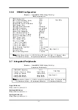
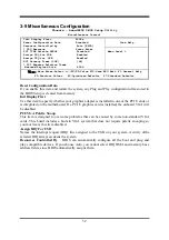
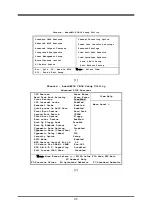
 
CAS # Latency 

When synchronous DRAM is installed, the number of clock cycles of CAS latency depends 
on the DRAM timing.    The settings are: Auto,3, 4 and 5. 

RAS-to-CAS Delay 

This field let’s you insert a timing delay between the CAS and RAS strobe signals, used when 
DRAM is written to, read from, or refreshed.   

Fast

 gives faster performance; and 

Slow

 gives 

more stable performance.    This field applies only when synchronous DRAM is installed in 
the system.     

Row Precharge Time 

If an insufficient number of cycles is allowed for the RAS to accumulate its charge before 
DRAM refresh, the refresh may be incomplete and the DRAM may fail to retain date.    Fast 
gives faster performance; and Slow gives more stable performance.    This field applies only 
when synchronous DRAM is installed in the system.   


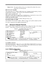
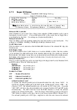
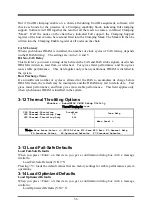
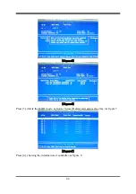
3-12 Thermal Throttling Options   

Phoenix – AwardBIOS CMOS Setup Utility


Thermal Throttling Op

tions  


Item Help 


CPU  Thermal-Throttling           Disabled 
CPU  Thermal-Throttling  Temp          70 

    CPU  Thermal-Throttling  Duty          50% 

 
  Menu  Level  > 


↑↓→←

 Move Enter:/-/PU/PD:Value F10:Save ESC:Exit  F1:General Help 

F5:Previous  Values    F6:Optimized  Defaults   F7:Standard  Defaults 


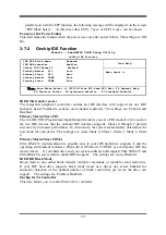
3-13 Load Fail-Safe Defaults 

Load Fail-Safe Defaults 

When you press <Enter> on this item, you get a confirmation dialog box with a message 
similar to: 

Load Fail-Safe Defaults (Y/N)? N 

Pressing <Y> loads the default values that are factory settings for stable performance system 
operations. 

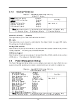
3-14 Load Optimized Defaults 

Load Optimized Defaults 

When you press <Enter> on this item, you get a confirmation dialog box with a message 
similar to: 

Load Optimized Defaults (Y/N)? N 

Summary of Contents for XBLUE-78GA2

Page 1: ...Processor NO G03 XBLUE78VA2 F Rev 1 0 Release date Aug 2008 Trademark Specifications and information contained in this documentation are furnished for information use only and are subject to change at any time without notice and should not be construed as a commitment by manufacturer ...

Page 2: ...ii Environmental Protection Announcement Do not dispose this electronic device into the trash while discarding To minimize pollution and ensure environment protection of mother earth please recycle ...

Page 3: ... THE MAIN MENU 22 3 4 STANDARD CMOS FEATURES 23 3 5 ADVANCED BIOS FEATURES 24 3 5 1 CPU FEATURE 24 3 6 ADVANCED CHIPSET FEATURES 26 3 6 1 PCIE CONFIGURATION 26 3 6 2 DRAM CONFIGURATION 27 3 7 INTEGRATED PERIPHERALS 27 3 7 1 SUPER IO DEVICE 28 3 7 2 ONCHIP IDE FUNTION 29 3 7 3 ONCHIP PCI DEVICE 30 3 8 POWER MANAGEMENT SETUP 30 3 9 MISCELLANEOUS CONFIGURATION 32 3 10 PC HEALTH STATUS 33 3 11 POWER U...

Page 4: ...D 780V Chipset motherboard User s Manual 5 CD for Motherboard Utilities 5 I O Back Panel Shield 5 SATA Cable 5 HDD Cable AMD K10 Processor Family Cooling Solutions As processor technology pushes to faster speeds and higher performance with increasing operation clock thermal management becomes increasingly crucial while building computer systems Maintaining the proper computing environment without ...

Page 5: ... RealTek RTL8111CVC PCI E Gigabit LAN which supports optional 10 100 1000Mbps data transfer rate And the embedded HD 6 channel ALC662 HD Audio CODEC is fully compatible with Sound Blaster Pro standards that offer you with the home cinema quality and satisfying software compatibility The AMD 780V Series motherboards deliver outstanding value and performance for gamers with a true bandwidth design f...

Page 6: ...creased to the preset idle percentage to cool down the processor When at throttling mode the beeper sound can be optionally selected to indicate it is in working For detail operating please read Section 3 11 Bi turbo Configuration CPU Smart Fan The Noise Management System It s never been a good idea to gain the performance of your system by sacrificing its acoustics CPU Smart Fan Noise Management ...

Page 7: ... locate the front panel jumpers to find the Power on jumper Reset Button You can easily restart the computer by pressing down this button for a few seconds without troubling yourself to locate the front panel jumpers to find the reset jumper G P I Function Green power indicator function The full name of G P I technology is Green Power Indicator technology obviously technology utilized to low power...

Page 8: ...s concurrent bandwidth Integrate IDE and Serial ATA2 RAID One IDE controllers support PCI Bus Mastering ATA PIO DMA and the ULTRA DMA 33 66 100 133 functions that deliver the data transfer rate up to 133 MB s for 2 IDE Devices and for 6 Serial ATA2 ports providing 300 MB sec data transfer rate with RAID 0 1 10 and JBOD functions Gigabit LAN Integrated RealTek RTL8111CVC PCI E 10 100 1000 LAN Suppo...

Page 9: ...ystem CPU Memory 1017 4069 2867 Graph HDD 4884 NG Content Creation Winstone 2004 33 7 Business Winstone 2004 22 5 Winbench 99 V2 0 Business Hi end GraphicWinmark99 243002 3 Business Hi end Graphic Winmark N A SISMark 2004 SISMark Rating Internet Content Creation Office Productivity SISMark 2007 269 165 3D Creation 238 331 Web publication E learning 248 Communication Document Creation 133 203 Data ...

Page 10: ...Power Connector Realtek ALC662 HD Audio Decode CDIN RTL 8111CVC Gigabit LAN Speaker Connector USB Port USB1 USB23 Power LED Connector AMD 780V Chipset SYSFAN2 Front Audio KBMB USB Power on JP1 IR Connector Reset Button Power PCI Express2 0 x16 by 4 lane SYSFAN1 HDMI SPDIF CPUFAN PCI Express2 0 x1 4 pin PWR Connector AMD 700 SB chipset USB RJ45 LAN PS 2 Mouse PS 2 Keyboard Line IN Line OUT MIC IN V...

Page 11: ...ers Header Name Description Page AUDIO1 SPEAKER MIC header 9 pin Block P 17 USB1 USB2 USB3 USB Port Headers 9 pin Block P 17 SPEAK1 PC Speaker connector 4 pin Block P 17 PWR LED1 PWR LED Power LED 3 pin Block P 17 JW_FP1 Reset HDLED Power Button PWR LED Front Panel Header including IDE activity LED Reset switch Power On Button lead 9 pin Block P 17 SYSFAN1 2 FAN Headers 3 pin Block P 18 CPUFAN FAN...

Page 12: ...Power On and Load Standard Default 8 Reboot 9 Install Operating System 10 Install Driver and Utility 2 2 Checking Motherboard s Jumper Setting 1 Keyboard USB function Enabled Disabled JP1 2 CMOS RAM Clear 3 pin JBAT A battery must be used to retain the motherboard configuration in CMOS RAM short 1 2 pins of JBAT to store the CMOS data To clear the CMOS follow the procedure below 1 Turn off the sys...

Page 13: ...PCI Express2 0 Peripheral Component Interconnect Express2 0 developed in 2003 the speed of each line doubled from the previous PCI E of 2 5Gbps to 5 Gbps Serial Port a low speed interface typically used for mouse and external modems Parallel Port a low speed interface typically used for printers PS 2 a low speed interface used for mouse and keyboards USB Universal Serial Bus a medium speed interfa...

Page 14: ...cooling FAN if necessary To install a CPU first turn off your system and remove its cover Locate the ZIF socket and open it by first pulling the level sideways away from the socket then upward to a 90 degree angle Insert the CPU with the correct orientation as shown below The notched corner should point toward the end of the level Because the CPU has a corner pin for two of the four corners the CP...

Page 15: ...hannel 1 NOTE When you install DIMM module fully into the DIMM socket the eject tab should be locked into the DIMM module very firmly and fit into its indention on both sides 2 5 Expansion Cards 2 5 1 Procedure For Expansion Card Installation 1 Read the documentation for your expansion card and make any necessary hardware or software setting for your expansion card such as jumpers 2 Remove your co...

Page 16: ...USB 3 HD Audio MC97 IMPORTANT If using PCI cards on shared slots make sure that the drivers support Shared IRQ or that the cards don t need IRQ assignments Conflicts will arise between the two PCI groups that will make the system unstable or cards inoperable 2 5 4 PCI Express Slot AMD 780V Series motherboard series offer one PCI Express2 0 x16 16 lane graphics slots and one PCI Express2 0 x16 by 4...

Page 17: ... power to the system board We recommend that you use an ATX 12V Specification 2 0 compliant power supply unit PSU with a minimum of 350W power rating This type has 24 pin and 4 pin power plugs If you intend to use a PSU with 20 pin and 4 pin power plugs make sure that the 20 pin power plug can provide at least 15A on 12V and the power supply unit has a minimum power rating of 350W The system may b...

Page 18: ...ors are for PS 2 keyboard and PS 2 Mouse 4 USB Port connector CN1 The connectors are 4 pin connector that connects USB devices to the system board 5 LAN Port connector UL1 for RJ45 LAN This connector is standard RJ45 connector for Network It supports 10M 100Mb 1000Mb s data transfer rate 6 Large 4 Pin Power Connector J2 Power Connector The connectors are 4 pin connector that supports extra 12V 5V ...

Page 19: ...rovided IDE hard disk ribbon cable After connecting the single plug end to motherboard connect the two plugs at other end to your hard disk s If you install two hard disks you must configure the second drive to Slave mode by setting its jumpers accordingly Please refer to the documentation of your hard disk for the jumper settings Primary IDE Connector Pin 1 IDE1 USB RJ45 LAN PS 2 Mouse PS 2 Keybo...

Page 20: ...d disks E SATA1 is not for SATA hard drive it is only for connecting to a SATA connector of the D SATA1 D SATA2 or D SATA3 to let the ESATA port work Serial ATA2 Port Connector SATA4 SATA6 SATA2 SATA1 SATA3 SATA5 2 6 2 Headers 1 Line Out MIC Header for Front Panel 9 pin AUDIO1 These headers connect to Front Panel Line out MIC connector with cable Line Out MIC Headers AUDIO Pin 1 AUD Lineout2 L AUD...

Page 21: ...s to the case mounted reset switch for rebooting your computer without having to turn off your power switch This is a preferred method of rebooting in order to prolong the lift of the system s power supply See the figure below 7 Power switch PWR BTN This 2 pin connector connects to the case mounted power switch to power ON OFF the system USB Port Headers Pin 1 USB1 VCC DATA GND DATA VCC OC DATA GN...

Page 22: ...f connector 9 CD Audio In Headers 4 pin CDIN1 CDIN are the connectors for CD Audio Input signal Please connect it to CD ROM CD Audio output connector 10 IR infrared module Headers 5 pin IR This connector supports the optional wireless transmitting and receiving infrared module You must configure the setting through the BIOS setup to use the IR function IR infrared module Headers IR Pin 1 GND IRRX ...

Page 23: ...only when your stereo system has digital input function 12 WI FI Header This header supports WI FI Function Connect the wireless local area network adapter to this header It allows you to create a wireless environment and enjoy the convenience of wireless network connectivity ADAPTER 1 2 HDMI_SPDIF_OUT GND SPDIF WI FI Headers WI FI Pin 1 D0 GND USB 5 N C D1 2 11 12 GND USB 5 D1 N C 3 3V D0 ...

Page 24: ...e system will then run power on test While the test is running the BIOS will alarm beeps or additional message will appear on the screen If you do not see any thing within 30 seconds from the time you turn on the power The system may have failed on power on test Recheck your jumper settings and connections or call your retailer for assistance Beep Meaning One short beep when displaying logo No err...

Page 25: ... right to choose in the main menu the option you want to confirm or to modify Press F10 when you have completed the setup of BIOS parameters to save these parameters and to exit the BIOS Setup menu Press Page Up Page Down or keys when you want to modify the BIOS parameters for the active option 3 1 Entering Setup Power on the computer and by pressing Del immediately allows you to enter Setup If th...

Page 26: ...it Without Saving Esc Quit F9 Menu in BIOS Select Item F10 Save Exit Setup Figure 3 1 Standard CMOS Features Use this Menu for basic system configurations Advanced BIOS Features Use this menu to set the Advanced Features available on your system Advanced Chipset Features Use this menu to change the values in the chipset registers and optimize your system s performance Integrated Peripherals Use th...

Page 27: ...8 Time hh mm ss 1 39 8 IDE Channel 0 Master None IDE Channel 0 Slave None SATA Channel 5 None SATA Channel 6 None SATA Channel 1 None SATA Channel 3 None SATA Channel 2 None SATA Channel 4 None Drive A 1 44M 3 5in Halt on All Errors Base Memory 640K Extended Memory 392194K Total Memory 393216K Menu Level Change the day month year and century Move Enter Select PU PD Value F10 Save ESC Exit F1 Gener...

Page 28: ...Up NumLock Status On Typematic Rate Setting Disabled Typematic Rate Chars Sec 6 Typematic Delay Msec 250 Security Option Setup APIC Mode Enabled MPS Version Control For OS 1 4 OS Select For DRAM 64MB Non OS2 HDD S M A R T Capability Disabled Full Screen LOGO Show Disabled Menu Level Move Enter Select PU PD Value F10 Save ESC Exit F1 General Help F5 Previous Values F6 Optimized Defaults F7 Standard...

Page 29: ...m from the devices in the sequence selected in these items The settings are Floppy LS ZIP HDD 0 HDD 1 HDD 3 SCSI CDROM LAD and Disabled Boot Up Floppy Seek During POST BIOS will determine if the floppy disk drive installed is 40 or 80 tracks 360K type is 40 tracks while 760K 1 2M and 1 44M are all 80 tracks Boot Up NumLock Status The default value is On On default Keypad is numeric keys Off Keypad...

Page 30: ...registers control most of the system options in the computer Phoenix AwardBIOS CMOS Setup Utility Advanced Chipset Features Item Help DRAM Configuration Press Enter HT Link Control Press Enter PCIE Configuration press Enter IGX Configuration Press Enter HDMI Audio Enabled NB Power Management Auto Memory Hole Disabled System BIOS Cacheable Disabled Menu Level Move Enter Select PU PD Value F10 Save ...

Page 31: ...75ns Write Recovery Time Twr 6 bus clocks Precharge Time 3 clocks Row Cycle Time 26 bus clocks RAS to RAS Delay Trrd 5 clocks Menu Level Move Enter Select PU PD Value F10 Save ESC Exit F1 General Help F5 Previous Values F6 Optimized Defaults F7 Standard Defaults 3 7 Integrated Peripherals Phoenix AwardBIOS CMOS Setup Utility Integrated Peripherals Item Help CMIX SB700 Revision 2 5 0 Superio Functi...

Page 32: ...d infrared chip The options are Full and Half default Full duplex means that you can transmit and send information simultaneously Half duplex is the transmission of data in both directions but only one direction at a time Onboard Parallel Port There is a built in parallel port on the on board Super I O chipset that Provides Standard ECP and EPP features It has the following option Disabled 3BCH IR...

Page 33: ...Master Slave PIO The two IDE PIO Programmed Input Output fields let you set a PIO mode 0 2 for each of the two IDE devices that the onboard IDE interface supports Modes 0 through 2 provide successively increased performance In Auto mode the system automatically determines the best mode for each device The settings are Auto Mode 0 Mode 1 Mode 2 Mode 3 Mode 4 Primary Master Slave UDMA Ultra DMA 33 i...

Page 34: ...d if your system contains a Universal Serial Bus USB controller and you have a USB device The settings are Enabled Disabled 3 8 Power Management Setup The Power Management Setup allows you to configure your system to most effectively save energy saving while operating in a manner consistent with your own style of computer use Phoenix AwardBIOS CMOS Setup Utility Power Management Setup Item Help AC...

Page 35: ...by PWRBTN Under ACPI Advanced Configuration and Power management Interface you can create a software power down In a software power down the system can be resumed by Wake up Alarms This item lets you install a software power down that is controlled by the power Button on your system If the item is set to Instant Off then the power button causes a software power down If the item is set to Delay 4 S...

Page 36: ...S Setup is cleared from memory Init Display First Use this item to specify whether your graphics adapter is installed in one of the PCI E slots or is integrated on the motherboard If a PCI E graphics card is installed the onboard VGA will be disabled PCI VGA Palette Snoop This item is designed to overcome problems that can be caused by some non standard VGA cards This board includes a built in VGA...

Page 37: ...ther Enabled or Disabled Shutdown Temperature This item can let users setting the Shutdown temperature when CPU temperature over this setting the system will auto shutdown to protect CPU PS CPU Smart FAN Configurations CPU Full Speed Temp This item allows you setting the FAN works in full speed when the temperature over the value which out set If the temperature below the value but over the Idle T...

Page 38: ... Reference clock 100 SB Reference clock 100 Spread Spectrum Enabled AMD K8 Cool Quiet Control Disabled VDIMM Select 1 95v NB Voltage setting 1 15v Memory Clock Mode Auto DRAM CLOCK at Next Boot DDR533 Menu Level CPU Clock at Next Boot Min 194 Max 600 Move ENTER Accept ESC Abort Move Enter Select PU PD Value F10 Save ESC Exit F1 General Help F5 Previous Values F6 Optimized Defaults F7 Standard Defa...

Page 39: ...w Control Mode enable will make the HT Link communication have the complex ordering rules for Isochronous source to make sure it can get service from the system with deterministic worst case latency However the latency time cost of ISOC flow control mode is an important consideration Normal flow control mode will be a simpler solution for most system HT Link Tristate Disabled mode will make the li...

Page 40: ...d in the system Row Precharge Time If an insufficient number of cycles is allowed for the RAS to accumulate its charge before DRAM refresh the refresh may be incomplete and the DRAM may fail to retain date Fast gives faster performance and Slow gives more stable performance This field applies only when synchronous DRAM is installed in the system 3 12 Thermal Throttling Options Phoenix AwardBIOS CM...

Page 41: ...lear any previously entered password from CMOS memory You will be asked to confirm the password Type the password again and press Enter You may also press Esc to abort the selection and not enter a password To disable a password just press Enter when you are prompted to enter the password A message will confirm that the password will be disabled Once the password is disabled the system will boot a...

Page 42: ...S 9X NT 2K XP Insert CD into your CD ROM drive and the MAGIC INSTALL Menu should appear as below If the menu does not appear double click MY COMPUTER double click CD ROM drive or click START click RUN type X SETUP EXE assuming X is your CD ROM drive From MAGIC INSTALL MENU you may take 8 selections 1 ATI install ATI driver pack 2 SOUND install ALC 662 HD Audio driver 3 LAN install RealTek LAN Cont...

Page 43: ... MENU 2 Click NEXT when ATI software driver pack appears 3 Click Yes to accept the license agreement and start installation 4 Choose whether you would like to restart and click Finish to restart your computer 5 Click Continue anyway 6 Choose Finish do not restart your computer ...

Page 44: ... INSTALL MENU appears 2 Click NEXT When Realtek High Definition Audio driver windows appear 3 Click FINISH and restart your computer 4 Manual Sound Effect Setting 5 Devices and mixer setting 6 Audio input and output setting 7 Microphone effect setting 8 3D demo setting ...

Page 45: ...3 LAN Install RealTek LAN Controller Driver 1 Click LAN when Magic Install Menu appears 2 Click Next to install RealTek LAN Driver 3 Click Install to begin the installation 4 After driver installation completed Click Finish 4 4 RAID Install SATA RAID Driver and Utility 1 Click RAIDDisk when MAGIC INSTALL MENU appears 2 Install RAID Disk ...

Page 46: ...internet security install shield wizard windows appears 3 This is license agreement select I accept the terms in the license agreement and Click NEXT 4 The preinstallation checkup process 5 Click Next after you select the features you want to install and the folder to install it 6 Click Install after you select to install the optional online services ...

Page 47: ...m the will not allow you to upgrade BIOS by Award Flash Utility If there is no such selection users can follow the 4 steps directly to update BIOS STEP 1 Prepare a boot disc You may make one by click START click RUN type SYS A click OK STEP 2 Copy utility program to your boot disc You may copy from DRIVER CD X FLASH AWDFLASH EXE or download from our web site STEP 3 Download and make a copy of the ...

Page 48: ...latform RAID Function Installation Please set these choice in the BIOS as RAID BIOS setup Integrated Peripherals Onchip SATA Device Onchip SATA Type When the below figures appeared please press Ctrl F into figure 2 figure1 Function press 1 key showing the RAID press 2 key building RAID press 3 key delete the RAID press 4 key showing the information of controller figure2 press 1 key showing the RAI...

Page 49: ...RAID 5 5 JBOD figure4 Choose LD 1 then press Enter Take Raid0 for example use to shift the cursor press space key to change the choice press Ctrl Y to keep Set Assignment mode as Y press Ctrl Y to keep then figure 5 appeared erase the MBR choose Ctrl Y figure 6 appeared Press any key finished the RAID ...

Page 50: ...46 figure5 figure6 Press 3 delete the RAID mode as figure 7 press Delete will delete the array As figure 7 figure7 Press 4 showing the information of controller as figure 8 ...

Page 51: ...Windows 2000 please insert Windows XP or Windows 2000 CD into the CD ROM drive Then remove the floppy diskette and boot the system At the very beginning you will see the message at the bottom of screen Press F6 if you need to install a third party SCSI or RAID driver At this moment please press F6 key and follow the instructions of Windows XP or Windows 2000 for the proper installation Execute Sta...

Page 52: ...ess Enter Hard Disk Boot Priority Press Enter Virus Warning Disabled CPU Internal Cache Enabled External Cache Enabled Quick power On Self Test Enabled First Boot Device Hard Disk Second Boot Device CDROM Third Boot Device Floppy Boot other Device Enabled Boot Up Floppy Seek Disable Boot Up NumLock Status On Typematic Rate Setting Disabled Typematic Rate Chars Sec 6 Typematic Delay Msec 250 Securi...

Page 53: ...Disabled VDIMM Select 1 95v NB Voltage setting 1 15v Memory Clock Mode Auto DRAM CLOCK at Next Boot DDR533 Menu Level Move Enter Select PU PD Value F10 Save ESC Exit F1 General Help F5 Previous Values F6 Optimized Defaults F7 Standard Defaults 3 Compatible with OS Windows XP 64 series Users must install CPU driver program AMD Processor Driver and select the Minimal item in Power Setting ...

Page 54: ...50 With OS Windows Vista series there is no need for to take more steps If needed please enter Power Settings to make corresponding changes ...

Reviews: