Baby Lock Jewel Service Manual
© Baby Lock, all rights reserved
21
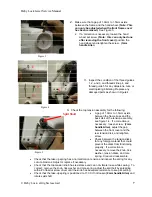
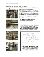
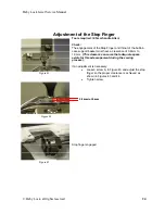
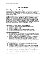
Figure 36
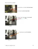
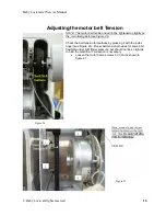
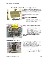
•
Push the head frame back against the main frame so that screw C touches the main
frame. Adjust screw C
(2mm handle Allen)
to bring the needle to center in the needle
plate.
•
Gently tighten screw E until it lightly touches the main frame.
•
Tighten screw D.
•
Repeat process on the left side of the head frame.
(Note: If needle position has changed, repeat process)
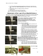
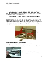
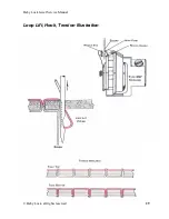
Adjustment of the Loop Lift and Needle Distance
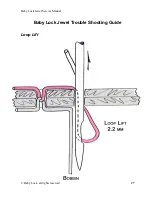
“Loop Lift” is a universal hook and timing term for all lock stitch sewing machines. When the needle lifts
a specified distance from the
BDC (bottom dead center)
, the hook point is set to coincide with the
needle as shown in figures 8.4 and 8.5
Tools required: (loop lift clamp, a 2.2mm forked feeler
gauge, and a #3 x 150 flat-slot screwdriver)
NOTE: The loop lift clamp used must have a plastic
protective compression pad, so as not to damage the
coating of the needle bar.
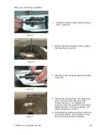
Check: (observe the following)
•
Turn the hand wheel until the needle bar is at its
lowest position or
BDC
.
•
Place the loop lift clamp (special protective clamp)
on the needle bar and set the thumbscrew lightly.
•
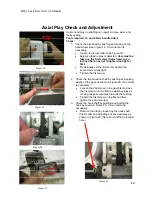
Place the 2.2mm feeler gauge between the clamp
and the projected bearing in the head frame (see
Figure 34).
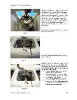
•
Raise and reset the clamp, pinching the 2.2 feeler
gauge in between the clamp and projected bearing.
This step may be repeated a few times to remove
all excess play between the clamp and gauge.
•
Remove the 2.2 feeler gauge (see Figure 35).
•
Rotate the hand wheel in the direction of motion until
the clamp touches the bearing (see Figure 36).
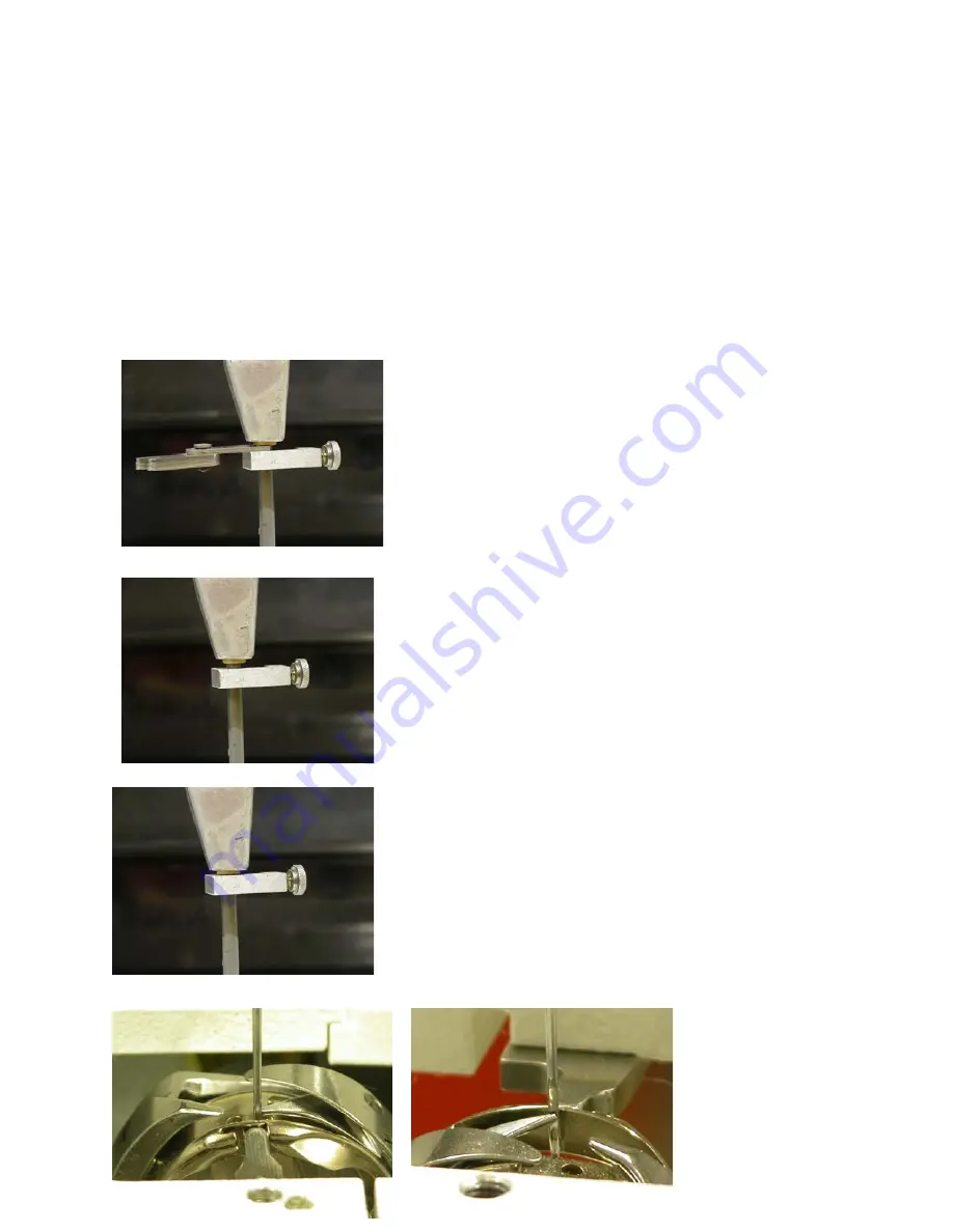
•
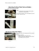
Check the position of the hook point relative to the
needle. (See Figures 37 A & B).
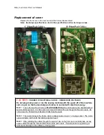
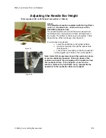
Note: When the hook screws have been loosened, the
adjustments of the loop lift and needle distance are possible
since the hook can be moved radically as well as axially.
If a correction is needed: 1st rotate basket down, see Figure 41 in
Adjusting Needle Height
section.
•
Loosen the screws on the hook base and set the
hook to the correct positions by sliding the hook
axially on its shaft, as well as radically, setting the
hook point relative to the needle (needle distance).
See note next page
.
7.0
Figure 34
Figure 35
Figure 37 A & B