
Baby Lock Jewel Service Manual
© Baby Lock, all rights reserved
25
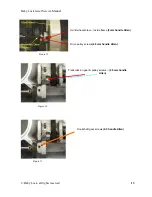
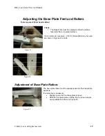
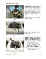
Figure 47
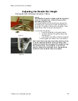
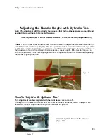
Adjusting the Needle Height with Cylinder Tool
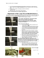
Note: The adjustment with the cylinder tool requires that the hook be removed, so loop lift and
needle distance will have to be reset afterwards.
Tools required: (#2 or #3 flat slot screwdriver x 150mm, Needle Height Cylinder tool)
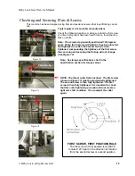
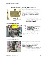
Check
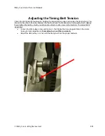
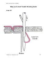
: Turn the hand wheel in the direction of motion until the hook point becomes even with the right
side of the needle as shown in (Fig 46). The hook point should be 1.0mm above the needle eye. If the
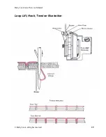
height of the needle appears to be out, install the Loop Lift Clamp and 2.2mm feeler gauge as shown in
the Adjustment of Loop Lift and Needle Distance Section, check loop lift. If the machine requires a
Loop Lift adjustment, remove the stop finger and hook body from the machine. Follow the steps using
the Needle Height Cylinder tool:
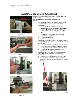
Needle Height with Cylinder Tool
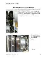
This adjustment can be completed with the front frame cover on or off.
The height of the needle must be set from the front side of the machine as shown. The eye of the
needle must align exactly to the trepan groove as shown in Figure 51.
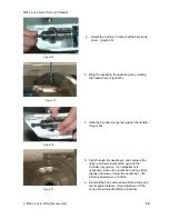
1. Install the Cylinder Tool with the flat side up.
(Figure 47)
1.0mm
Figure 46


