2. CONNECTION AND TEST DRIVING
2. CONNECTION AND TEST DRIVING
CONNECTION TO THE TRACTOR
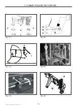
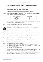
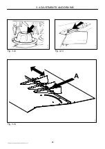
First, the machine should be adjusted to the track width of the tractor.
Fig. 2-1
You can choose between 3 settings (A, B and C) of the pins on the headstock
corresponding to the following track width sizes.
Track width [mm]
Pin position
< 1650
A
1650 – 1850
B
> 1850
C
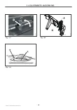
The adjustment of the pins is made by loosening and adjusting the fixed pin and
adjusting the loose pin according to fig. 2-2.
Fig. 2-2
Choose middle hole B in the lever arm I at the left coupling point.
WARNING:
Category III link arms can in hole A break the spring tightener
Fig. 2-1
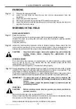
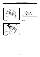
Connect the link arms of the tractor to the coupling points D of the machine.
Fig. 2-3
Mount the top link F so that it is approximately parallel with the link arms of the
tractor.
Thereby a suitable movement is achieved when lifting the machine with the link arms
and optimal conditions for later connection and disconnection of the machine.
Fig. 2-4
Connect the hydraulic hoses to a double-acting hydraulic outlet.
Place the machine in working position by first raising the link arms, then activate the
double-acting outlet, and at the same time actuate the valve by pulling the cord.
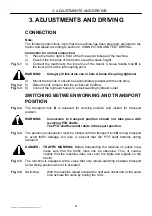
Fig. 2-5
Release the transport lock B.
Fig. 2-6
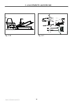
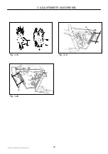
Adjust the relief of the machine as follows:
1) Place the handle for the double-acting hydraulic outlet in floating position.
2) Raise/lower the link arms of the tractor until the indicator A is on level with the
arrow on the transfer B.
3) Lock the link arms in this position.
A lighter machine (lower ground pressure) is obtained by raising the link arms so the
indicator A moves approximately 1 cm down towards + on the transfer B.
A heavier machine (higher ground pressure) is obtained by lowering the link arms so
the indicator A moves approximately 1 cm up towards - on the transfer B.
PIGB-093X-06 GX 2402/2802/3202 SM-GX 2402/2802 SC 0410
17

