2. CONNECTION AND TEST DRIVING
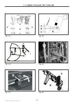
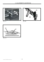
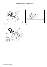
Fig. 2-7
Adjust the length of the top link so the headstock B is vertical.
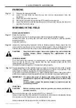
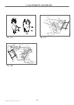
Fig. 2-8 Adjust the length of the PTO drive shaft so that it in working position has minimum
200 mm overlapping on the profile tubes, in no position is compressed more than the
prescribed 30 mm in order not to bottom the shaft, and in the longest position has
minimum 100 mm overlap.
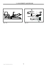
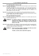
Fig. 2-9 Fasten the PTO drive shaft half parts to PTO and PIC, respectively, when these are
at the same horizontal level and opposite each other (the shortest distance on this
machine). Hold the shaft ends parallel to each other and mark the 30 mm (minimum).
CAUTION:
Shorten all 4 tubes equally. The ends of the profile tubes MUST
be rounded off outside and inside. Burrs MUST be removed
carefully.
Grease the tube carefully before reassembling. If the shafts are
not greased, they are exposed to big friction forces if e.g. the
shock absorbing system is activated during the transmission of
heavy load.
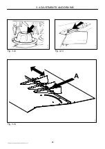
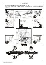
Fig. 2-10 The PTO shaft has an internal greasing system A which makes it possible to grease
the profile tubes B at C without disassembling the shaft.
Due to this greasing system you can shorten the shaft 100 mm maximum, which is
the distance to the grease bush D.
In extreme cases where further shortening is necessary, you have to shorten at the
other side of the bush, and the greasing system must be dismounted. After this the
tubes are greased by disassembling the 2 half parts.
IMPORTANT: For the warranty of the PTO shaft to be valid, and to retain the
durability, the following rules must be observed.
•
Always start the machine with the engine running at low speed.
•
Always start the machine with the PTO shaft in a position of
maximum 10
o
from horizontal.
•
A sudden increase in the number of rpm of the machine, e.g.
when driving into the crop after turning in the field, must only take
place with the PTO shaft in a position of maximum 10
o
from
horizontal.
•
Last, but not least: Grease the PTO shaft and especially its profile
tubes every 8 working hours, minimum.
FRICTION CLUTCH
On some models the PTO shaft has an integral friction clutch. Its purpose is to
secure the transmission against overload when working in the field and when starting
the machine (connection of the power take-off (PTO)).
The friction clutch must be “aired” before starting a new machine. See section 5.
MAINTENANCE – FRICTION CLUTCH, and do this during test driving.
TEST DRIVING
When all guards are in place and the machine is in working position, a test drive can
be made.
Before connecting the PTO, check if all tools have been removed from the machine
and that no persons are near. Connect the PTO shaft carefully and let the engine run
at low number of rpm for some minutes. If there is no unintended noise or unusual
vibrations, the speed can be increased to normal number of RPM.
Apart from the tractor driver nobody should stand near the machine.
PIGB-093X-06 GX 2402/2802/3202 SM-GX 2402/2802 SC 0410
19

