background image

Montageanleitung

Set-up Instructions

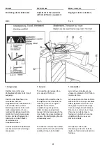
Montage

Nach der Montage der 
Schutzbügel und des 
Schwadtuches (Bild 2) können 
STOLL-Schwader in min-trans-
Stellung (schmale Transportbreite 
von 1,60 m) im Dreipunktanbau 
sofort ins Feld gefahren werden. 

After the installation of the windrow 
cloth as shown in fig. 2 the three-
point "mini-trans" STOLL 
windrowers (narrow transport width 
of 1,60 m) can immediately be 
used in the field. 

Après le montage des protecteurs 
et de la toile d'andainage (fig. 2) 
les andaineurs STOLL peuvent 
être attelés, sans préparatifs 
ultérieurs, au relevage 3-points du 
tracteur et transportés, en position 
"mini-trans" (= largeur de transport 
étroite de 1,60) vers le champ. 

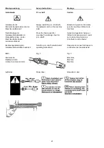
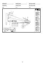
Mit einfachen Handgriffen werden 
vor Arbeitsbeginn die einzelnen 
Zinkenträger Z auf die bereits 
serienmäßig montierten Lagerrohre 
L aufgesteckt und mit 
Klappsplinten K gesichert. 

Before the start of operations it is 
merely necessary to install, with a 
few handles only, the rotor arms Z 
to the pre-assembled supporting 
tubes L and to secure with the 
safety pins K. 

Avant de commencer le travail, on 
aura simplement à attacher les 
bras portedents Z sur les tubes de 
montage L déjà prévus en série, ce 
qui ne requiert que peu de 
manipulations. Ne pas omettre 
d'assurer les bras porte-dents au 
moyen des goupilles automatiques 
K.

Zuvor ist der Farbschutz auf dem 
Steckrohr gemäß A 661 (im 
Beipack) zu entfernen und der 
Moosgummiring aufzuschieben. 

Before installing the rotor arms 
remove the protective paint layer 
from the bearing tube (see A 661) 
and install the rubber ring.

 Avant ce montage on aura soin 
d'éliminer la peinture de protection 
sur les tubes (voir A 661) ainsi que 
de mettre en place les anneaux en 
caoutchouc spongieux.

Danach werden nach 
Herausziehen des 
Federsteckbolzens F die 
Schutzbügel gemeinsam mit dem 
bereits montierten Schwadtuch M 
heruntergeschwenkt und in dieser 
unteren Stellung mit dem 
Federsteckbolzen F wieder 
gesichert.

Remove spring safety pin F, unfold 
the safety frames with the swathing 
deflector M already installed and 
secure safety frames in lowered 
position with spring safety pin F.

Retirer l'axe débrochable à ressort 
F, déployer les protecteurs avec 
toile d'andainage M montée et les 
assurer dans cette position à l'aide 
de l'axe décrochable à ressort F.

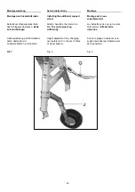
Zur Schwadtuch-Umstellung 
Federstecker G am Schwadtuch-
Tragrohr S herausnehmen, am 
Schwadtuch-Halter H und 
Schwadtuch M gemeinsam nach 
vorn schieben, um 90° in 
Arbeitsstellung schwenken und 
wieder nach hinten schieben, 
anschließend wieder mit 
Federstecker G sichern.

To change over the swathing 
deflector to working position, 
remove R-clip G from support tube 
S, move support H with swathing 
deflector M to the front, pivot 90° 
into working position and move 
again to the rear. 

Pour mettre la toile d'andainage en 
position de travail, retirer la 
goupille élastique G du tube 
support S, déplacer en avant le 
support H avec toile d'andainage 
M, l'orienter de 90° en position de 
travail et le déplacer de nouveau 
en arriere. Remettre en place la 
goupille élastique G.

Kreisel-Verdrehsicherung V nach 
Lösen der Griffmutter R um 180° 
nach oben schwenken und 
Griffmut-ter R wieder anziehen. 

Secure with R-clip G. Release knur-
led nut R, pivot rotor lock V 180° to 
the top and tighten knurled nut R.

Après avoir desserré l'écrou 
moleté R, orienter le verrou V de 
180° vers le haut. Resserrer l'écrou 
moleté R. 

Transportarretierungsbügel T für 
Zinkenarme verbleibt an der 
Maschine. Sicherung durch 
Klappsplint K.

The bar T which secures the rotor 
arms in transport position remains 
on the machine and has to be 
secured with safety pin K.

Le verrou T qui sert à immobiliser 
les bras porte-dents en cours de 
transport, reste sur la machine où il 
sera assuré à l'aide de la goupille 
automatique K.

20

Summary of Contents for R 335 DS

Page 1: ...Maschine auf der innenseite des Umschlages Please note the serial number of your machine at the inside of the cover Veuillez noter le numero de Votre machine sur la face interne de la couverture G lti...

Page 2: ...e travail Pi re de noter ici le num ro de s rie de votre machine Ceci vous sera utile lorsque vous commanderez des pi ces Le Num ro de s rie est place dans le cadre indiqu sur la figure Gelieve bij ee...

Page 3: ...nische Daten 17 Technical Data 17 D tails techniques 17 Montageanleitung 18 Set up Instructions 18 Indications de montage 18 Lieferumfang 18 Extent of supply 18 Volume de livraison 18 Montage der Schu...

Page 4: ...Inform your dealer of any discrepancies Informez votre concessionnaire d s que quelque chose n est pas reglementaire Vor Inbetriebnahme die Betriebsanleitung und die Sicherheitshinweise lesen und beac...

Page 5: ...rgeschriebenen Betriebs Wartungs und Instandhaltungsbedingungen Under declined use the manufacturer s prescribed operation maintenance and repair conditions are to be adhered to La r glementation pr v...

Page 6: ...Bestimmungsgem e Verwendung Declined use of the machine Reglementation d utilisation 6...

Page 7: ...unction before beginning with the operation Doing this during operation would be too late 4 Avant le d but de travail se familiariser avec tous les dispositifs et l ments de commande et avec leurs fon...

Page 8: ...m ssen so verlegt sein da sie in allen Transport und Arbeitsstellungen nicht unbeabsichtigte Bewegungen ausl sen 15 Operating appliances ropes chains rods etc of remote controlled appliances have to l...

Page 9: ...eitsbereich und Gefahrenbereich ist verboten 22 Never stay in the turning and slewing area of the implement 22 Le stationnement dans la zone d action de l outil est interdit 23 Nicht im Dreh und Schwe...

Page 10: ...len 3 There is danger of in the area of the three point linkage by its squeezing and shearing places 3 Dans la zone des bras du relevage il y a risque d accident par crasement ou cisaillement 4 Bei Be...

Page 11: ...T O shafts with overload or overrunning clutches which are not covered through a protect appliance at the tractor attach overload resp overrunning clutches to the machine 5 En utilisation d arbres art...

Page 12: ...er it has come to a full standstill 13 Aussit t l arr t attention la rotation d e l inertie Durant ce temps ne pas s approcher de l apparail Ne le faire que quand il est vraiment immobile 14 Beseitige...

Page 13: ...unting tyres requires sufficient knowledge and availability of prescribed tools 2 Le montage de pneumatiques demande une connaissance suffisante et des outils appropries 3 Reparaturarbeiten an Reifen...

Page 14: ...nt d l ments de travail avec un tronconneuse utiliser une machines conforme et mettre des gants de protection 5 le Fette und Filter ordnungsgem entsorgen 5 Dispose of old oils grease and filters as pr...

Page 15: ...len beweglichen Teilen versehen In dieser Betriebsanleitung sind zur Kenntlichmachung einzelner Teile oder Montagevorg nge auf den Abbildungen verschiedene Schutzvorrichtungen abgenommen worden Niemal...

Page 16: ...ieu avanc vers les peignes support par des roues mont es en pneus ballon influence directement la pr cision et la stabilit de l appareil en cours de travail Die Einstellung der Arbeitstiefe erfolgt be...

Page 17: ...he Daten Technical Data D tails technique Ger uschemissionswert am Arbeitsplatz 70 dB A Noise emission value measured at the operators position 70 dB A Niveau sonore messur sur le poste de conduite 70...

Page 18: ...ssai Maschine auf R der stellen Maschine mit Palette nach hinten auf die beiden R der schwenken 2 Mann oder Hebezeug notwendig Place machine onto wheels swing machine with pallet to the rear onto both...

Page 19: ...prings onto the windrow former frame with rail N between both using 13 round headed screws M6x16 washers 7 and locknuts M6 O Bolt the windrow former onto support P using the top central or bottom set...

Page 20: ...Schutzb gel gemeinsam mit dem bereits montierten Schwadtuch M heruntergeschwenkt und in dieser unteren Stellung mit dem Federsteckbolzen F wieder gesichert Remove spring safety pin F unfold the safety...

Page 21: ...an der Maschine Kettenhaken zusammendr cken Press the chain pole after mounting the retaining chain for p t o shaft Apr s montagede la chaine sur l arbre de transmission du 3 point ou de la machine fe...

Page 22: ...Montage der Zinkenverlustsicherung Installation of the tine loss prevention device Montage des s curit sur dents Bild 4 Fig 4 Fig 4 22...

Page 23: ...n Attach chain G to the tractor top link The chain must sag sufficiently La cha ne G se fixe sur le 3 points c te tracteur Elle doit tre d tendue H heneinstellung am St tzradstiel durch abstecken mit...

Page 24: ...es der Doppelfederzinken The height of the machine has to be adjusted so that the tines just touch the ground Too high an adjustment involves an unsatisfactory pick up action whilst too deep an adjus...

Page 25: ...e Zur Stra enfahrt wird der Gelenkbock wie folgt verriegelt For transport position lock the headstock as follows Pour le transport sur route il faut verrouiller la t te comme suit Griff A nach hinten...

Page 26: ...Schmierplan Greasing chart Plan de graissage Schmierplan Greasing chart Plan de graissage Bild 7 Fig 7 Fig 7 26...

Page 27: ...und bei Einstellarbeiten Maschine immer abschalten Caution Always stop the machine to lubricate or to make any adjustments Attention Toujours arreter la machine pour graisser ou ajuster Schmieranweis...

Page 28: ...Aufkleber Decalcomania Decalcomanie 28...

Page 29: ...in soll Ihr Gewicht wird w hrend des Transports auf der Stra e im wesentlichen von dem Fahrzeug getragen Anbauger te k nnen Front Zwischenachs Aufbau Heck oder Seitenger te sein Heckanbauger te d rfen...

Page 30: ...1 Tafeln Folien oder Anstriche mit einer Kantenl nge von mindestens 282 mm x 564 mm oder 423 mm x 423 mm oder in begr ndeten Ausnahmef llen von mindestens 141 mm Breite und 800 mm H he mit unter 45 na...

Page 31: ...tgewicht des Anh ngers das Gesamtgewicht des ziehenden Fahrzeugs nicht bersteigt und die St tzlast des Anh ngers vom Anbauger t mit einem oder mehreren St tzr dern so auf die Fahrbahn bertragen wird d...

Page 32: ...erschiedliche Abst nde zum Ger teheck haben 4 16 3 4 auf Leuchtentr gern angebracht sein Die Leuchtentr ger d rfen aus 2 oder wenn die Bauart des Ger tes es erfordert aus 3 Einheiten bestehen wenn die...

Page 33: ...33...

Page 34: ......

Page 35: ......

Page 36: ...44 20 183 E mail EA stoll jf de Dealer W I L H E L M S T O L L Maschinenfabrik GmbH Postfach 3 38266 Lengede Bahnhofstr 21 38268 Lengede Telefon Allgemein 0 53 44 20 0 Telefax Verkauf 0 53 44 20 182 E...

Reviews: