User’s Manual
22
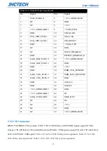
Table 2.13: Mini-PCIe pin assignments
Pin
Signal
Pin
Signal
1
PCIE_WAKE_N
2
+V3.3_MINICARD2
3
NC
4
GND
5
NC
6
+V1.5
7
+V3.3_MINICARD2
8
+VUIM_PWR
9
GND
10
UIM_DATA
11
PCIe_MINI_CLK5-
12
UIM_CLK
13
PCIe_MI
14
UIM_RESET
15
GND
16
+VUIM_VPP
17
NC
18
GND
19
NC
20
WIFI2_DISABLE#
21
GND
22
PLTRST_MINIPCIE_N
23
SATA_RXP
24
+V3.3_MINICARD2
25
SATA_RXP_PCIE17-
26
GND
27
GND
28
+V1.5
29
GND
30
SMB_CLK_RESUME
31
SATA_TXN_PCIE17-
32
SMB_DATA_RESUME
33
SATA_TXN
34
GND
35
GND
36
USB_N6
37
GND
38
USB_P6
39
+V3.3_MINICARD2
40
GND
41
+V3.3_MINICARD2
42
NC
43
SATA_PCIE0_DET
44
SIM1_DET
45
NC
46
NC
47
NC
48
+V1.5
49
NC
50
GND
51
NC
52
+V3.3_MINICARD2
2.3.12 M.2 connector
BRAV-7520/BRAV-7521 provides 3*M.2, 1*M.2 2280 M-Key with PCIeX4 signal, support NVMe
storage; 1*H-M.2 B-Key 3052 with SIM slot and USB signal, support 5G wifi; 1*H-M.2 E-Key
2230 with USB signal.
Table 2.14 for M.2 2280 M-Key pin assignments. Table 2.15 for M.2
3052 B-Key pin assignments. Table 2.16 for M.2 2230 E-Key pin assignments.
Summary of Contents for BRAV-7520
Page 1: ...User s Manual BRAV 7520 7521 User s Manual Ver A0 1 Date 20 Oct 2020 ...
Page 2: ...User s Manual Version Note No Ver Note Date Writer 1 A0 1 first publish 20201020 Echo ...
Page 8: ...User s Manual iii SYSTEM RESOURCE 52 5 1 WDT and GPIO 53 ...
Page 9: ...User s Manual 1 General Information CHAPTER 1 ...
Page 17: ...User s Manual 9 BRAV 7520 Fornt Figure 1 7 BRAV 7521 Fornt Figure 1 8 ...
Page 19: ...User s Manual 11 Hardware Installation CHAPTER 2 ...
Page 38: ...User s Manual 30 ...
Page 43: ...User s Manual 35 ...
Page 44: ...User s Manual 36 BIOS Setup CHAPTER 3 ...
Page 57: ...User s Manual 49 Driver Installation CHAPTER 4 ...


