background image


User’s Manual


2.3.4 COM1_SEL 

COM1_SEL are used to configure the Serial COM ports to RS232 or RS485. 


Figure 2.7 

Pins 

Function 

RS485_SIN1 

SIN1 

SSIN1 

Note:when COM1_SEL selected,COM1_SEL1 must be set in accordance to COM1_SEL1 

2.3.5 COM3_SEL 

COM3_SEL are used to configure the Serial COM port to RS232 or RS485. 


Figure 2.8 

Pins 

Function 

RS422 

SIN3 

RS485 


2.4 I/O indication 

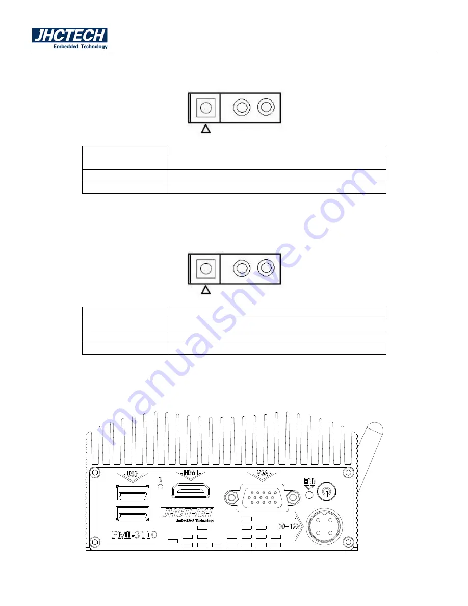
Front view 


Figure 2.9 

Summary of Contents for PMI-3110

Page 1: ...MI 3110 1 Aluminum case Fanless disign 2 Intel Celeron J1900 3 1xDDR3L 1333 DIMM max 8GB 4 1xmSATA 1x2 5inch HDD 5 1xminipcie with SIM card support 3G LTE 6 DC 12V input 7 VGA HDMI display 8 2COM 2USB Audio 9 2 Intel I210IT Gigabit Ethernet 10 HDD Anti vibration design ...

Page 2: ...User s Manual 2 Version Note No Ver Note Date Writer 1 A1 0 first publish 20150510 Jie Deng 2 A1 1 Add installation 20150723 Wei Li 3 A1 2 Revise the max memory capacity 20151123 Wei Li ...

Page 3: ...tended to be accurate and reliable However ShenZhen JHC Technology Co Ltd assumes no responsibility for its use nor for any infringements of the rights of third parties which may result from its use Acknowledgements Award is a trademark of Award Software International Inc IBM PC AT PS 2 and VGA are trademarks of International Business Machines Corporation Intel and Pentium are trademarks of Intel ...

Page 4: ...ent materials service time and freight Please consult your dealer for more details If you think you have a defective product follow these steps 1 Collect all the information about the problem encountered For example CPU speed JHC products used other hardware and software used etc Note anything abnormal and list any onscreen messages you get when the problem occurs 2 Call your dealer and describe t...

Page 5: ... when the equipment is operated in a commercial environment This equipment generates uses and can radiate radio frequency energy and if not installed and used in accordance with the instruction manual may cause harmful interference to radio communications Operation of this equipment in a residential area is likely to cause harmful interference in which case the user will be required to correct the...

Page 6: ...ndication 9 2 4 1 Ethernet Connector LAN 10 2 4 2 Power Input Connector DC IN 11 2 4 3 USB 2 0 Connector 11 2 4 4 COM1 Connector 12 2 4 5 COM2 Connector 12 2 5 Installation 13 2 5 1 HDD SSD Installation Only for PMI 3110 S002 13 2 5 2 Memory chip Installation 14 2 5 3 MSATA MINIPCIE 3G WIFI Installation 15 BIOS Setup 16 3 1 BIOS Setup 17 3 2 Entering Setup 17 3 3 Main Setup 17 3 3 1 System date Sy...

Page 7: ...es and Exit 29 3 8 2 Discard Changes and Exit 29 3 8 3 Save Changes and Reset 29 3 8 4 Discard Changes and Reset 29 3 8 5 Save Changes 29 3 8 6 Discard Changes 30 3 8 7 Restore Defaults 30 3 8 8 Save User Defaults 30 3 8 9 Restore User Defaults 30 3 8 10 Boot Override 30 Driver Installation 31 4 1 Follow the sequence below to install the drivers 32 4 2 Installation 32 ...

Page 8: ...User s Manual 1 General Information CHAPTER 1 ...

Page 9: ...minipcie with SIM card support 3G LTE Half size 6 DC 12V input 6 VGA HDMI display 7 2USB 8 4 LAN Switcher S002 1 Aluminum case Fanless disign 2 Intel Celeron J1900 3 1x DDR3L 1333 DIMM max8GB 4 1xmSATA 1x 2 5inch SATA HDD 5 1xminipcie with SIM card support 3G LTE Full size 6 DC 12V input 6 VGA HDMI display 7 2COM 2USB Audio 8 2 Intel I210 Gigabit Ethernet 9 HDD Anti vibration design 1 3 Specificat...

Page 10: ... to DC 12 V 5 A 60 W 1 3 5 Power Requirement System power Minimum power input DC 12 V 3 A 1 4 Environmental Specifications Operating temperature 20 70 C With extended temperature mSATA devices 10 50 C With standard temperature mSATA HDD devices Relative humidity 95 60 C non condensing Storage temperature 40 85 C 40 185 F Vibration loading during operation With SSD mSATA 3 Grms IEC 60068 2 64 rando...

Page 11: ...User s Manual 4 PMI 3110 S002 Dimensions Figure 1 1 ...

Page 12: ...User s Manual 5 Hardware Installation CHAPTER 2 ...

Page 13: ...is the simplest kind of electrical switch It consists of two metal pins and a small metal clip often protected by a plastic cover that slides over the pins to connect them To close a jumper you connect the pins with the clip To open a jumper you remove the clip Sometimes a jumper will have three pins labeled 1 2 and 3 In this case you would connect either pins 1 and 2 or pins 2 and 3 Figure 2 1 Th...

Page 14: ...User s Manual 7 Figure 2 3 ...

Page 15: ...set PWRON_SEL1 pins 2 and 3 to On If you want to use the power button set pins 1 and 2 to On Figure 2 4 Pins Function 1 NC 2 SB_BTN 3 AUTO 2 3 2 COM1_PWR1 COM1_PWR1 are used to configure the Serial COM ports to pure RS232 or RS232 with power Figure 2 5 Pins Function Pins Function 1 NRI 1 2 NRI 1 3 V5S 4 NRI 1 5 V12S 6 NRI 1 2 3 3 COM1_SEL1 COM1_SEL1 are used to configure the Serial COM ports to RS...

Page 16: ...Figure 2 7 Pins Function 1 RS485_SIN1 2 SIN1 3 SSIN1 Note when COM1_SEL selected COM1_SEL1 must be set in accordance to COM1_SEL1 2 3 5 COM3_SEL COM3_SEL are used to configure the Serial COM port to RS232 or RS485 Figure 2 8 Pins Function 1 RS422 2 SIN3 3 RS485 2 4 I O indication Front view Figure 2 9 ...

Page 17: ...d with two Intel WGI211 for 10 100 1000Mbps Ethernet controllers The Ethernet port provides a standard RJ 45 jack connector with LED indicators on the front side to show its Active Link status Green LED and Speed status white LED Table 2 2 for pin assignments Figure 2 10 Ethernet Connector ...

Page 18: ...or Pin Assignments Pin Signal Name 1 12V DC IN 2 12V DC IN 3 GND 4 GND 2 4 3 USB 2 0 Connector The PMI 3110 can support up to six USB interface connectors These USB interface connectors give complete Plug Play and hot swap capability for up to 127 external devices The USB interface complies with USB UHCI Rev 2 0 compliance The USB inter face can be disabled in the system BIOS setup The USB interfa...

Page 19: ...tting of COM1 is RS 232 Please refer to Table 2 5 for their pin assign ments and jumper settings for setting up RS 485 1 2 3 4 5 6 7 8 9 Figure 2 13 COM3 COM4Connector RS 232 RS 485 Pin Signal Name Signal Name 1 DCD DATA 2 RxD DATA 3 TxD NC 4 DTR NC 5 GND GND 6 DSR NC 7 RTS NC 8 CTS NC 9 RI NC Note NC represents No Connection 2 4 5 COM2 Connector The PMI 3110 provides a RS 232 ports by a D sub 9 p...

Page 20: ... 2 6 COM1 2 5 6 Serial Port Pin Assignments Pin Signal Name 1 DCD 2 RxD 3 TxD 4 DTR 5 GND 6 DSR 7 RTS 8 CTS 9 RI 2 5 Installation 2 5 1 HDD SSD Installation Only for PMI 3110 S002 a Use the cross screwdriver demount the screws on bottom cover as below Figure 2 15 Figure 2 16 ...

Page 21: ...uction paste on the hard disk drive as below Figure 2 17 Figure 2 18 c Fix the ready mounting bracket on the bottom cover with 4 cross pan head srews M3 5mm and then insert the hard disk drive cable into hard disk drive as shown in figure Figure 2 19 Figure 2 20 2 5 2 Memory chip Installation Insert a memory chip at a 30 degree angle into the main board memory slot as shown in Figure Thick 1 5mm ...

Page 22: ...ke a MSATA MINIPCIE insert it into the main board as below Figure 2 23 Figure 2 24 b Use the cross screwdriver to fix the bottom cover as shown in figure Figure 2 25 MSATA position MINIPCIE 3G WI FI position Notice Pay attention to the direction of bottom cover Pls installation correctly ...

Page 23: ...User s Manual 16 BIOS Setup CHAPTER 3 ...

Page 24: ... Setup program that allows users to modify the basic system onfiguration This information is stored in flash ROM so it retains the Setup information when the power is turned off 3 2 Entering Setup Turn on the computer and then press F2 or DEL to enter the Setup menu 3 3 Main Setup When users first enter the BIOS Setup Utility users will enter the Main setup screen Users can always return to the Ma...

Page 25: ... Time or System Date using the Arrow keys Enter new values through the keyboard Press the Tab key or the Arrow keys to move between fields The date must be entered in MM DD YY format The time must be entered in HH MM SS format 3 4 Advanced BIOS Features Setup Select the Advanced tab from the PMI 3110 setup screen to enter the Advanced BIOS Setup screen You can select any of the items in the left f...

Page 26: ...erial port 1 Serial Port 2 Configuration This item allows users to configure serial port 2 Serial Port 3 Configuration This item allows users to configure serial port 3 Serial Port 4 Configuration This item allows users to configure serial port 4 Serial Port 5 Configuration This item allows users to configure serial port 5 Serial Port 6 Configuration This item allows users to configure serial port...

Page 27: ...e display all information about system Temperature Voltage 3 4 3 CPU Configuration Figure 3 6 CPU Configuration Limit CPUID Maximum Disabled for Windows XP Execute Disable Bit XD can prevent certain classes of malicious buffer overflow attacks when combined with a supporting OS ...

Page 28: ...A SATA Enable Disable Serial ATA SATA Mode Select IDE AHCI Serial ATA Port 0 Port1 Enable Disable Serial ATA Port0 Port1 SATA Port 0 Port1 HotPlug Enable Disable SATA Port0 Port1 hotplug function Figure 3 7 IDE Configuration 3 4 5 Miscellaneous Configuration OS Selection When installing and using the operating system the item need to set up correctly Such as installing or using the Windows 7 you m...

Page 29: ...User s Manual 22 Figure 3 8 Miscellaneous Configuration 3 4 6 CSM Configuration Figure 3 9 CSM Configuration CSM Support Enable Disable CSM Support ...

Page 30: ...on ROM IMMEDIATE execute the trap right away POSTPONED execute the trap during legacy boot Boot option filter This option controls Legacy UEFI ROMs priority Network Controls the execution of UEFI and Legacy PXE OpROM Storage Controls the execution of UEFI and Legacy Storage OpROM Video Controls the execution of UEFI and Legacy Video OpROM Other PCI devices Determines OpROM execution policy for dev...

Page 31: ...only for EFI applications 3 5 Chipset Configuration Select the Chipset tab from the PMI 3110 setup screen to enter the Chipset BIOS Setup screen You can display a Chipset BIOS Setup option by highlighting it using the Arrow keys All Plug and Play BIOS Setup options are described in this section The Plug and Play BIOS Setup screen is shown below Figure 3 11 Chipset Configuration ...

Page 32: ... s Manual 25 3 5 1 North Bridge Figure 3 12 North Bridge Intel IGD Configuration Config Intel IGD Settings Max TOLUD Maximum Value of TOLUD 3 5 2 Intel IGD Configuration Figure 3 13 Intel IGD Configuration ...

Page 33: ...xed Graphics Memory size used by the Internal Graphics Device DVMT Total Gfx Mem Select DVMT 5 0 Total Graphic Memory size used by the Internal Graphics Device ISP Enable Disable Open or close the ISP devices ISP PCI Device Selection For Windows startup PCI Device set as B0D2F0 For Linux startup PCI Device set as B0D3F0 3 5 3 South Bridge Figure 3 14 South Bridge Azalia Controller Enables or disab...

Page 34: ...p main BIOS setup menu All Security Setup options such as password protection is described in this section To access the sub menu for the following items select the item and press Enter Change Administrator User Password Select this option and press ENTER to access the sub menu and then type in the password ...

Page 35: ...rs to select the number of seconds to wait for setup activation key Bootup NumLock State Select the Power on state for Numlock Quiet Boot If this option is set to Disabled the BIOS displays normal POST messages If Enabled an OEM Logo is shown instead of POST messages Boot Option 1 Sets the system boot order ...

Page 36: ... any permanent changes to the system configuration 3 8 3 Save Changes and Reset When users have completed system configuration select this option to save changes exit the BIOS setup menu and reboot the computer to take effect of all system configuration parameters 3 8 4 Discard Changes and Reset Select this option to quit Setup without making any permanent changes to the system configuration and r...

Page 37: ...um system performance but may not work best for all computer applications In particular do not use the Optimal Defaults if the user s computer is experiencing system configuration problems 3 8 8 Save User Defaults When users have completed system configuration select this option to save changes as user defaults without exit BIOS setup menu 3 8 9 Restore User Defaults The users can select this opti...

Page 38: ...User s Manual 31 Driver Installation CHAPTER 4 ...

Page 39: ...ou install the driver automatically Step 2 Install VGA Driver 1 Click on the Step 2 Intel Graphics Media Accelerator Driver Production Version folder and select the OS folder your system is 2 Double click on the Setup exe file located in each OS folder 3 Follow the instructions that the window shows 4 The system will help you install the driver automatically Step 3 Install LAN Driver 1 Click on th...

Reviews: