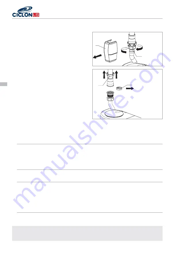
7.4. REPLACEMENT / CLEANING OF THE DISCHARGE NON-RETURN VALVE.
Before beginning the replacement / cleaning,
carry out a number of discharge cycles and (if
one has been installed) close the vertical drainage
pipe’s throttle valve and disconnect the unit from
the electricity supply.
- Remove the cover
and the 1
¼
” nut
.
- Loosen the clips of the discharge pipe brace in
order to be able to move the tube and thus enable
its disassembly.
- Prepare a container to collect the water, empty
the discharge pipe, activating the flapper of the
non-return valve.
- Remove the clip nut
- Check or replace the seal non-return joint
assembly.
- Follow the steps in reverse order to assemble the
valve.
Carry out a number of discharge cycles of the unit
before putting it back in service in order to eliminate
the air from the discharge installation.
8. TECHNICAL SPECIFICATIONS.
Inlets:
Top:
2 1
½
” x 40 mm inlets for Ø40 / 32 mm * smooth pipes
Lower side:
2 1
½
” x 40 mm inlets for Ø40 / 32 mm * smooth pipes
with non-return valve
Upper side:
1 1
½
” x 40 mm inlet for Ø40 / 32 mm * smooth pipes with
non-return valve.
* Five 40 to 32 conical reducing joints are supplied.
Outlet:
Discharge:
Ø32 mm for PVC pipe.
Non-return valve:
1
¼
” x 32 mm removable.
Pump:
Voltage:
~ 220/230 V, AC, 50 Hz.
Fuse:
Thermal.
Power:
0.39 kW.
Capacitor:
10 µF
Electrical connection:
For IEC standard
Maximum discharge height:
7 m
Maximum horizontal discharge distance:
72
Dimensions and weight:
Dimensions:
413 x 180 x 270.5 mm
Weight:
7.6 Kg
Weight including packaging:
8.9 Kg
12 - MODE D’EMPLOI ET ENTRETIEN
LIFTING STATION EB-705
English
NOTE: As a result of the constant improvement and development of our products, the data provided in this
maintenance and instruction manual may be modified without prior notice. This maintenance and instruc-
tion manual has no contractual value and all the information is given in good faith.
TO RETIRE EMBELLECEDOR
NON-RETURN JOINT
RENOVE CLIP NUT
REMOVE 1
¼
”
NUT


