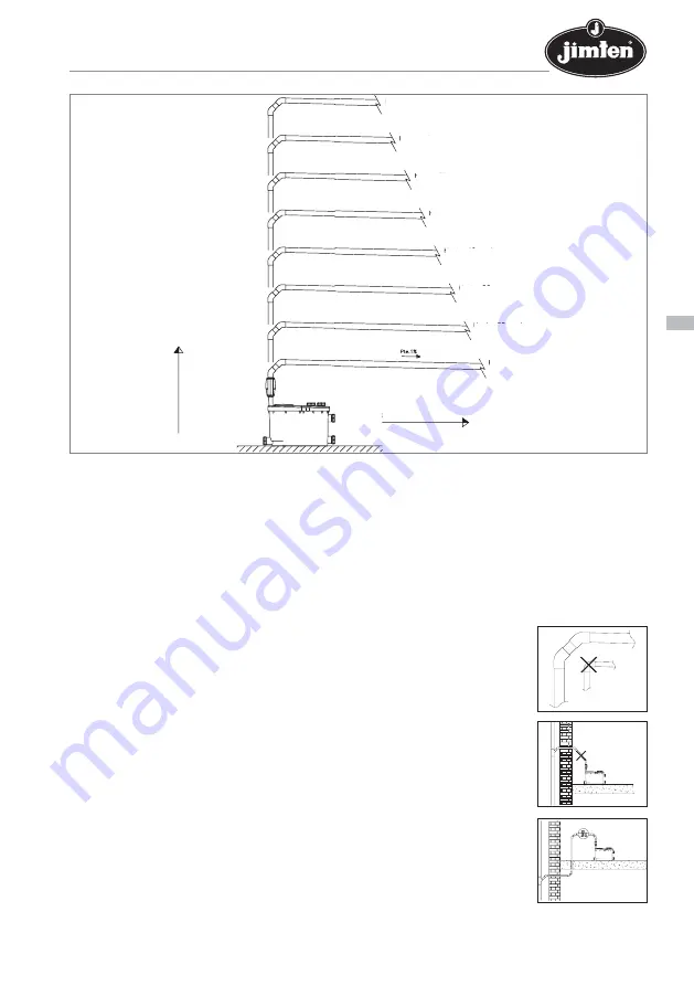
5.1. INSTALLATION RECOMMENDATIONS.
PIPING – Use Ø 32 mm PVC piping for discharge propulsion. Avoid curved sections (siphons) that
could retain certain solids and create obstructions.
PIPE SUPPORTS – The drainage pipes must be supported with the right accessories, according to
the manufacturer’s instructions.
BENDS – Do not use 90º elbows, use bends instead. If bends are not available, it is possible to use
two 45º elbows instead.
AVOID DIAGONAL SECTIONS – The installation sections must always be vertical or horizontal, never
install diagonal sections.
PROTECTION AGAINST FROST – In areas where there is a risk of frost due to
low temperatures, all stretches of pipe that are at risk of freezing must
be protected with thermal insulation.
CONNECTION WITH THE DOWNPIPE – Carry out the connection with the down-
pipe by means of a 45º bypass. If the joint with the downpipe is below the
base of the lifting station, a ventilation valve (Jimten A-69 type) must be
connected at the highest point of the installation to stop it emptying.
DISCHARGE – The discharge section must always be connected to the
drainage network or grey water tank. It is not recommended that the
water go into open drains or similar.
VENTILATION – The lifting station must not be enclosed by walls or in such a
way that the motor is prevented from being correctly ventilated by
means of the ventilation system incorporated.
SANITARY FIXTURES – The lifting station is prepared for the connection of up to
5 sanitary fixtures and appliances (washbasin, bidet, shower, bathtub,
MMAINTENANCE AND INSTRUCTION MANUAL - 7
LIFTING STATION EB-705
English
7 m.
6 m.
5 m.
4 m.
3 m.
2 m.
1 m.
0 m.
Up to 2 m.
Up to 12 m.
Up to 22 m.
Up to 32 m.
Up to 42 m.
Up to 52 m.
Up to 62 m.
Up to 72 m.
HORIZONTAL RANGE
VERTICAL RANGE


