17
Furthermore, the installation of an external relay is good
because this increases the galvanic separation between
the solenoid and the controller. Another advantage is that
the relay can bequickly changed in case of breakdown.
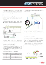
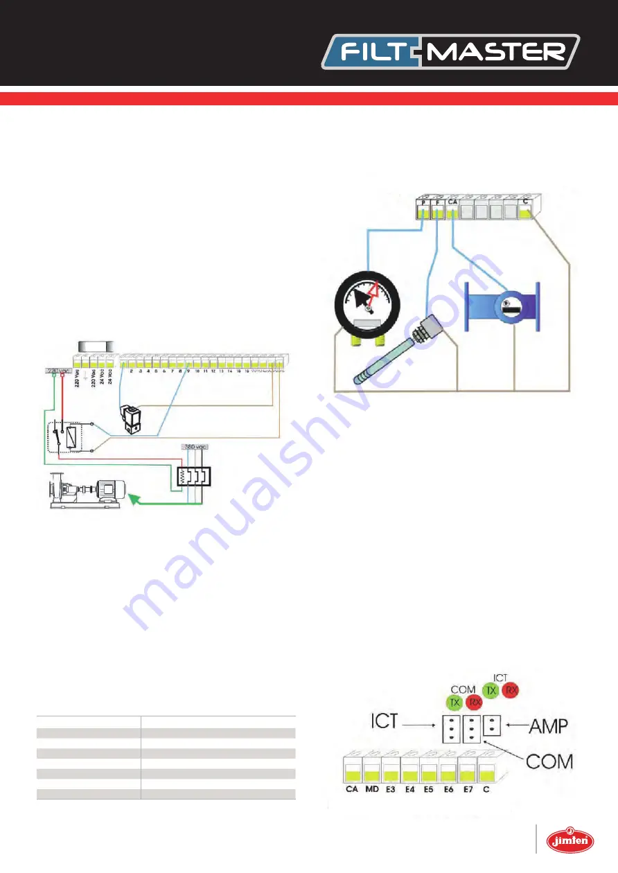
The devices shown on the previous table are those in the
following diagram:
In the previous diagram, we see the connections to the
water meter and the differential pressure gauge. These
inputs are fixed for these devices.
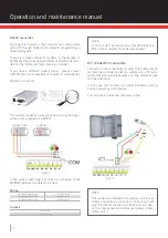
Electric connection to pumps
In addition to the controller, backwash valves and fil-
ters, there are other devices (pumps, mixers, fertilizer
pumps, etc.).
These elements are based on electric motors, and so
their installation and control follow common guidelines.
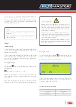
Communication connections
The controller can communicate with different devices:
There are 3 connector types located immediately above
the connection terminal block of the digital inputs.
There are 4 warning lights that inform us whether the
controller is sending or receiving information (from mo-
dem or ICT), useful information for setup and assistance
operations.
Input connection terminal block
The controller has 7 contact voltage-free inputs, that is
to say, the controller recognises them when there is a
short circuit between the common input and the corres-
ponding input.
The function of these inputs is the following:
The previous diagram is valid both for the automation
of pump motors, mixers and electric fertilizer injection
pumps.
Symbol
Function
P
MECHANICAL DIFFERENTIAL PRESSURE SWITCH
F
NETWORK WATER SENSOR/ACTIVE PUMPING
WM / CA
WATER METER
E4
-----without use-----
E5
-----without use-----
E6
-----without use-----
E7
-----without use-----
INPUTS
INPUTS
1,6 Amp

