Tilga Insert
8
Tilga Insert
9
Installation
(Continued)
Operating your Jindara
3000mm
3000mm
3000mm
1000mm
min if clear
within
3000mm of
flue top
Increase from
1000mm min
until clear
within 3000mm
of flue top
600mm min
More than 3000mm
600mm min
More than 3000mm
or less
3000mm
or less
Increase as
necessary
until
nothing
within
3000mm of
flue top
Any nearby
structure
3000mm
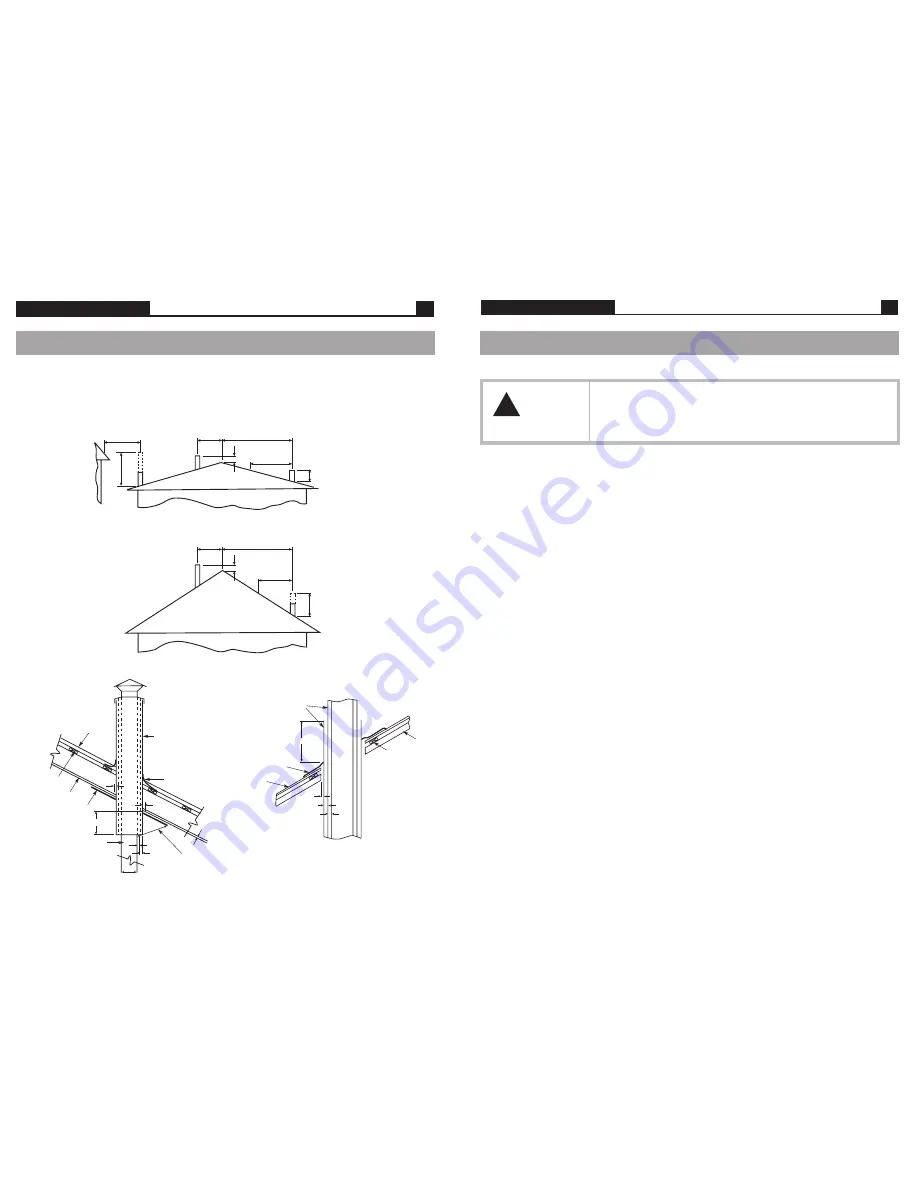
The flue pipe shall extend not less than 4.6m above the top of the floor protector. Note: Installation must be
carried out by a licensed installer in accordance with AS/NZS 2918:2001.
Flue pipe casing
Flashing
3 x flue diameter
from active flue to
heat sensitive
surface
Batten
Flue
pipe
Flashing
Flue pipe casings
Heat sensitive roof
25mm
25mm
25mm
Flue pipe
Gap 25mm
Gap 25mm
Roofing
Batten
Ceiling
Ceiling Plate
See clause 4.6.3(b) of AS/NZS 2918:2001
25mm
12mm
25mm
150mm dia
Example of sloped ceiling penetration
Example of roof penetration
Rafter
See clause 4.8 of AS/NZS 2918:2001
Flue and chimney requirements
Figure 7
Figure 8
WARNING
!
DO NOT ATTEMPT TO OPERATE THIS APPLIANCE WITHOUT READING AND
UNDERSTANDING THESE OPERATING INSTRUCTIONS THOROUGHLY. FAILURE TO
OPERATE THIS APPLIANCE PROPERLY MAY CAUSE UNDUE DAMAGE TO THE
APPLIANCE OR RESULT IN A FLUE FIRE.
Read these instructions
Starting your fire
Place a firelighter or paper in the bottom of the firebox and place a large amount of small kindling on top. Ignite the
paper or the firelighter. Set the air control to high and leave the main door open approximately 25mm. When the kindling
is burning, place about four pieces of small wood on top of the burning kindling. Once the wood is alight, close the main
door. After approximately 20 minutes, turn the air control down to medium. For fan operation refer page 10.
On the initial fire up you may detect smoke coming from the paint finish and from any oils that may be on the steel on
the outside of the firebox. This is normal. It is suggested to well ventilate your home on the initial fire up. Please refer to
our section ‘Paint Curing and Care’ on page 2.
The glass door
Always operate your heater with the door closed and locked. The only time you can leave the door open is on initial
lighting, or when reloading the heater.
Care of your glass
If you are burning good dry wood, you will have very little discolouration of your glass in normal burning cycle. If you aim
for an eight to ten hour overnight burn, you should not get much discolouration. You can control this by adjusting the air
control, moving from the left and slowly creeping the control to the right. After a number of days you will find the right
position to suit your requirements and the fuel that you are using.
Daily operations
When you get up in the morning, open up the air control of the heater to high position to start the embers glowing. Place
three or four pieces of wood on top of the embers and leave the door open 25mm. Once the fuel starts to flame close the
door. Depending on your daily heating requirements, operate the fan as per fan operation instructions on page 10.
For best results it is best to burn 410mm long wood and load your wood straight into the firebox front to rear. This will
give optimum efficiency and recoverable heat, and minimise creosote formation and smoke emissions.
Overnight burn
Approximately 30 minutes before turning the heater down for the overnight burn it is recommended to load the heater with
fuel. Leave the air control in the medium to high position. Let the heater run for about 30 minutes. This will reduce the
moisture content in the fuel before shut down. (This will help reduce the creosote formation in the firebox and flue.)
Set the air control to the setting you have found best for your requirements. Turn the fan off or to the thermostat control
position and retire. The aim when overnight burning is to have only a few hot embers left in the bottom of the firebox in
the morning, not huge lumps of wood.


