background image


USER’S MANUAL


4/14 


1. Safety Precaution 

-The safety recommendations outlined in this section are to be read, understood 

and followed before operating the product. 

-  Keep  this  information  in  a  safe  place  for  future  reference.  Failure  to  comply 

with any of the following safety procedures could result in serious hazard. 


1.1. Set up and General Handling Precaution 

1. 

Please set up the monitor in clean area where there is no dust. 

2. 

Do not set up the monitor on shaky stand, on incline surface or   

surfaces subject to frequent vibration. 

3. 

This monitor is intended for indoor use only. 

4. 

Do not press heavily the TFT-LCD panel with sharp objects,   

such as nails. 

5. 

When set up the monitor, be extremely careful.   

You may get injured from the sharp parts, such as steel covers 

6. 

When transporting the monitor, hold the body with both hands and 

letting LCD screen goes up. 

7. 

Do not lift the monitor up with holding LCD panel itself. 

8. 

The fluorescence lamp of LCD panel includes mercury.   

Do not waste or bury illegally. When waste, follow the related   

laws and regulations. 


1.2. Operating Precaution 

1. 

Do  not  place  the  monitor  in  areas  subject  to  direct  sunlight  and 

radiators or heat registers. Fire or electrical shock may result. 

2. 

Do  not  cover  the  vents  on  the  monitor  cabinet.  Bad  ventilation 

may cause a breakdown or fire. 

3. 

Do not remove cover(or back). This could result electrical shock. 

Refer servicing to qualified service personnel. 

4. 

If you find any abnormal issue or failure  while  you are  using this 

equipment, immediately unplug the power cable and contact your 

retailer or Jinyoung Contech Support Help Desk. 

5. 

Do not take apart or modify the equipment for any purpose.   

Fire or electrical shock may result. 

6. 

Never spill liquid of any kind on the monitor. Do not place in areas 

where there is high humidity and water splashes. 

7. 

Do not plug in/unplug the power cable with wet hands.   

Fire or electrical shock may result. 

8. 

Do  not  plug  the  monitor  into  outlets  with  voltage  other  than  the 

specified voltage. Incorrect voltage may result in  fire or electrical 

shock. 

9. 

Do not pull the plug out by the wire.


This may cause an electric 

shock or fire. 

10. 

Make sure that the power cable is firmly plugged in and not loose. 

Fire or electrical shock may result. 

11. 

Unplug the power cable for safety when not in use the monitor for 

a long period of time, such as long weekend or moving it. If dust 

accumulates in this area, it may result in fire. 

9. 

Do not connect too many extension cords or plugs to an outlet. 

Fire or electrical shock may result. 

10. 

Use only a properly grounded plug and receptacle. 

11. 

Do  not  spill  flammable  liquid  on  the  monitor.  Fire  or  electrical 

shock may result. 

12. 

Set  up  the  outlet  in  areas  where  close  to  the  monitor,  easily 

accessible and easily operative.   


1.3. Cleaning of the equipment and management   

Precaution 

1. 

Do not take apart or modify the monitor.   

Fire or electrical shock may result. 

2. 

When cleaning the monitor, always unplug the power. 

3. 

When cleaning the monitor, do not use flammable liquids, such as 

alcohol, benzene or thinners.   

4. 

If  you  strongly  wipe  down  the  surface  of  the  monitor  with  a 

sponge  and  a  piece  of  cloth,  in  case  of  plastic  equipment,  the 

coating may be fallen away. 

5. 

When  cleaning  the  monitor  case  or  the  surface  of  the  TFT  LCD, 

wipe with a slightly moistened, soft fabric.         

6. 

If the cleaning inside of the monitor is necessary, please contact 


Jinyoung Contech Support Help Desk.


Summary of Contents for INOV17V-T

Page 1: ...sued Date 2011 01 26 Human Computer Interface TO Ver 1 0 501 222 12 MARIOTOWER GURO DONG GURO KU SEOUL KOREA TEL 82 2 890 6400 FAX 82 2 890 6406 HOME PAGE http www jyct com Page 14Pages 17 TFT LCD Monitor INOV17V T USER S MANUAL ...

Page 2: ...USER S MANUAL 2 14 Revision History Date Rev No Contents Page 11 01 26 1 0 Initial ...

Page 3: ...4 Install and General Handling Precaution Operating Precaution Cleaning and Management Precaution 4 4 4 Introduction 5 Graphics input Modes supported 5 Specification 6 Block Diagram 7 LCD DISPLAY SYSTEM Adjustments 8 and Settings Connector 12 Dimensions 14 ...

Page 4: ... 5 Do not take apart or modify the equipment for any purpose Fire or electrical shock may result 6 Never spill liquid of any kind on the monitor Do not place in areas where there is high humidity and water splashes 7 Do not plug in unplug the power cable with wet hands Fire or electrical shock may result 8 Do not plug the monitor into outlets with voltage other than the specified voltage Incorrect...

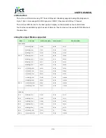
Page 5: ... 640x480 72 Hz 37 861 72 809 31 500 640x480 75 Hz 37 500 75 000 31 500 SVGA 800x600 56 Hz 35 156 56 250 36 000 800x600 60 Hz 37 879 60 317 40 000 800x600 72 Hz 48 077 72 188 50 000 800x600 75 Hz 46 875 75 000 49 500 XGA 1024x768 60 Hz 48 363 60 004 65 000 1024x768 70 Hz 56 476 70 069 75 000 1024x768 75 Hz 60 023 75 029 78 750 1152x864 75 Hz 67 500 75 000 108 000 1280x960 60 Hz 60 000 60 000 108 00...

Page 6: ...0 000 Hours Input Signal PC Connectivity Analog RGB 0 7Vpp 10 75 Ohms Standard Input Source DVI D Single Link CVBS 1 Channel S VHS 1 Channel Display Functions OSD Functions Power AC DC ADAPTER Adapter Input Voltage Range AC 100 240 VAC 50 60Hz DC out and Monitor Input Voltage 12 Vdc 3 5A Max Environmental Considerations Storage Temperature 20 60 C Operating Temperature 0 50 C Dimensions W x H x D ...

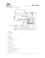
Page 7: ...Keypad Board 7 Keypad Control Cable 8 DC12 V Power Input Adaptor or Power Module 9 PC Analog VGA Input 10 DVI D Input 11 Composite Video Input CVBS 12 S Video Input 13 Touch Control data IN OUT Option 14 Touch Controller Option 14 1 Touch Controller Power Cable DC5V or DC12V Option 14 2 Touch Screen DATA Cable Option 14 3 Touch Controller Interface Cable Option 15 Touch Screen ...

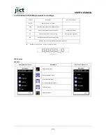
Page 8: ...em Input Source Change UP Increase setup value or move cursor up AUTO Analog Input Only DN Decrease setup value or move cursor down HOT KEY Function is only available while OSD menu is OFF Input Source Select VGA DVI CVBS S Video OSD Function MAIN MENU Analog RGB Input Source MAIN MENU DVI Video Input Source Enter COLOR Menu Enter IMAGE SET Menu Enter POSITION Menu DVI Video Input Not Support Ente...

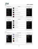
Page 9: ...ture Auto Adjustment Not Supported at DVI Input CVBS Input Source COLOR MENU S VIDEO Input Source Adjust Contrast Adjust Brightness Adjust Hue Adjust Saturation IMAGE SET Analog RGB Input Source IMAGE SET MENU DVI VIDEO Input Source Adjust Image CLOCK Not Supported at DVI Video Input Adjust Image Phase Not Supported at DVI Video Input Adjust GAMMA Adjust Sharpness ...

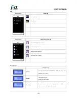
Page 10: ...ted at DVI Video Input Only Analog RGB Input Source Adjust the Image Vertically Not Available in DVI Video mode Image Auto Adjustment Not Supported at DVI Video Input OSD MENU All Input Source OSD MENU Adjust the OSD Menu Horizontally Adjust the OSD Menu Vertically Adjust the amount of OSD menu display time ...

Page 11: ...ource Select Composite Input Source Select Super Video S VIDEO Warning Message Warning Message No Signal When there is no VGA Signal R G B H SYNC V SYNC from PC or when DPMS function is activated No Cable Check cable connections Analog RGB or DVI Support Out of Range This issue may occur if the signal from the video adapter exceeds the scan range of the monitor Analog RGB or DVI Support ...

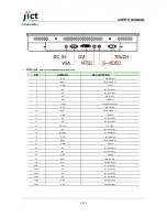
Page 12: ...9 RX1 T M D S Data 1 10 RX1 T M D S Data 1 11 GND Ground 12 NC No connection 13 NC No connection 14 DVI_ 5V 5V Power 15 NC No connection 16 Hot Plug Hot Plug Detect 17 RX0 T M D S Data 0 18 RX0 T M D S Data 0 19 GND Ground 20 NC No connection 21 NC No connection 22 GND Ground 23 RXC T M D S Clock 24 RXC T M D S Clock 25 C1 NC No connection 26 C2 NC No connection 27 C3 NC No connection 28 C4 NC No ...

Page 13: ...IN Horizontal sync or composite sync input 14 VS_IN Vertical sync input 15 D_SCL DDC serial clock CVBS Input RCA Right Angle Yellow PIN SYMBOL DESCRIPTION 1 CVBS Composite Video Signal Input 2 GND Ground S VHS Input Mini Din 4pin PIN SYMBOL DESCRIPTION 1 S C_IN Croma Input 2 GND Ground 3 GND Ground 4 S_Y_IN Luminance Input Power DC 12 V Input Jack DC Power jack 2 5mm contact pin diameter PIN DESCR...

Page 14: ...USER S MANUAL 14 14 ...

Reviews: