Jinyuan Lighting
15
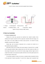
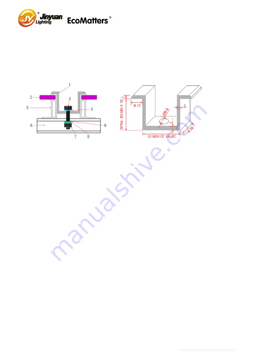
Figure 5. Clamp A: clamp for terminal modules(X=frame thickness)
1. Clamp B 2.Laminated piece 3.Aluminum frame 4.Bolt
5.Spacer 6.Installation bracket 7. Nut 8.Spring Shim 9.Spacer
Figure 6. Clamp B: clamp for middle modules
8. Electrical Installation
8.1 General Installation Rules
Normally the module may generate more electricity than standard condition. When
deciding the PV system component, with the parameters associated with rated voltage, wire
rated current, fuse model numbers and module output power,etc, do consider the actual
installation environment and conditions.
Please make sure the electrical components such as connector and inverter are in
disconnection during the installation.
Photovoltaic system can be formed with several modules in series and then in parallel,
which is especially suitable for higher voltage requirement. When the modules are in series, the
total voltage of the system is the sum total of each module voltage. And when higher current is
required, the modules can be organized in parallel, with total current of the system equal to the
sum total of each module current.
The maximum quantity for module to be in series or parallel should be calculated according
to the requirement of relevant regulations. The open circuit voltage under the expected local


