Jinyuan Lighting
18
conducting to the grounding device with proper dimension or to a bracket as an integrated
grounding device. There are grounding hole(Ø4) and grounding mark on the aluminum frame,
which are not used for fixing module. Extra holes are prohibited to be drilled on the module.
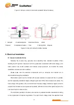
Grounding screws, spacers and nuts should be stainless steel material. Bend the
grounding wire into shape
Ω
and fix it between the screw head and spacers. Grounding screw
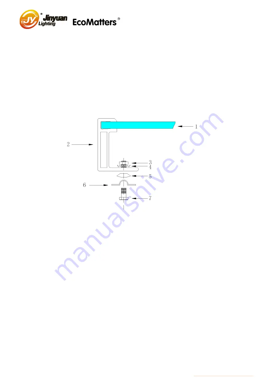
penetrates the grounding hole. The toothed lock washer should be installed to penetrate the
anodic oxide film of the aluminum frame to make sure a safe and reliable grounding effect.
1. PV module 2. Aluminum frame 3. Nut 4. Toothed lock washer
5.Cup shape washer 6. Grounding connector 7. Bolt
Figure 9 Equipotential Connection Diagram
The PV module can do the grounding with modules connected to the bracket as an
integrated grounding device or additional ground equipment. But all these grounding measures
should be safe and effective, and can not cause the electrochemical corrosion between the
aluminum frame of the module and the other different metals.
In order to obtain the best output power and avoid the PID effect, the DC negative of the
module array should be earthed when installing the modules. If this rule is not followed during
the installation, the output power of the system may be lowered.
Joint the module with field installation equipotential connection conductors and grounding
conductors. The connector or junction of the module should be marked with below special
identifier, any other connector or junction can not use this symbol

