PAGE 77 of 177
CX0344 Rev 05.3
TIP:
The probe holder yoke can accommodate many different probe and
wedge sizes of varying widths. It is best to centre the wedge with the
yoke’s pivot axis to reduce wedge tipping when scanning. Position the
inner probe holder arm accordingly with the centre of the yoke (Fig. 171).
7.
Position the wedge on the inner probe holder arm
(Fig. 172)
.
8.
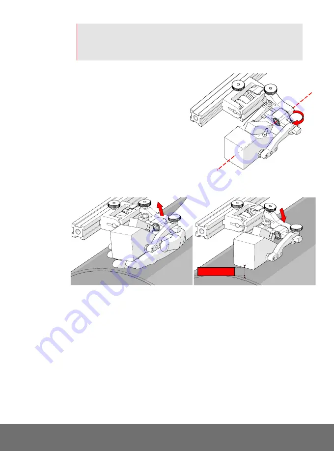
Slide outer probe holder arm
along the yoke pinching the
wedge in place.
9.
Tighten probe holder arm
adjustment knob
(Fig. 173)
.
5.7.8.2 Probe Holder Adjustment
To adjust the probe holder, follow these
steps:
1.
Ensure probe holder is in latched, upper position
(Fig. 174)
. If the probe holder
is already latched, it will only move within the slip joint adjustment range and
have no spring tension.
2.
Push the probe holder yoke down toward the inspection surface until the
wedge is approximately 6
mm
(¼ in)
from the inspection surface
(Fig. 175).
Fig. 173 - Pinch wedge with arm
Fig. 174 - Lift to latched position
Fig. 175 - Lower to scanning surface
6
mm
approx.


