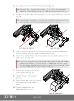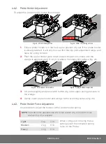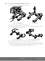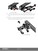
PAGE 10 of 42
3.
Using the supplied 3 mm hex driver, screw the rear pivot to the cart
(Fig. 30).
4.
Rotate the pivot to the original position and lock the side mounted lever
(Fig. 31).
4.4. Pivot Buttons
Available in a variety of shapes
and sizes fitting various wedge
dimensions.
Use the supplied 3/8 wrench
(Fig. 15)
to remove and install
pivot buttons in the desired hole
location
(Fig. 32)
.
4.5. Frame Bar
Frame bars
(Fig. 33)
are used to mount
probe holders, probe positioning systems
and other accessories.
Frame bars are available in a variety of
lengths
(see - Frame bar on page 10)
.
Fig. 30
- Screw to scanner body
2
1
Fig. 31
- Return pivot position
1
2
Fig. 32
- Pivot buttons
Fig. 33
- Frame bar


