PAGE 59 of 142
DN0108 Rev 00
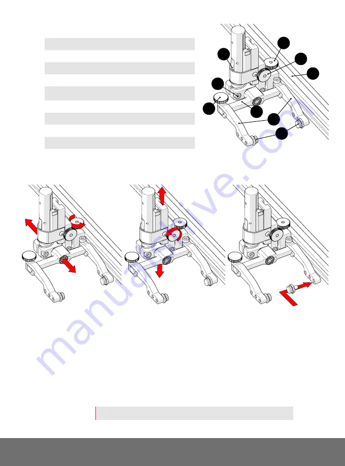
5.9.2. Vertical Probe Holder
A
Latch
B
Probe Holder Adjustment Knob
C
Vertical Adjustment Knob
D
Pivot Buttons
E
Probe Holder Arms
F
Yoke
G
Probe Holder Arm Adjustment Knob
H
Transverse Adjustment Screw
I
Frame Bar
5.9.2.1 Probe Holder Setup
To mount a UT wedge in the probe holder, follow these steps:
1.
The probe holder adjustment knob allows the probe holder to be
attached to a frame bar, as well as horizontal positioning on a frame bar
(Fig. 126)
.
2.
The vertical adjustment knob allows the vertical probe holder height
adjustment
(Fig. 127)
.
3.
Position the pivot buttons where necessary. When a narrow scanning
footprint is required, use the pivot button holes closet to the yoke
(Fig. 128)
.
TIP:
Probe pivoting may be impeded when closer to the yoke.
D
E
H
F
G
B
C
I
A
Fig. 125 - Vertical probe holder
Fig. 126 - Adjust on frame bar
Fig. 127 - Vertical adjustment
Fig. 128 - Place buttons


