PAGE 66 of 142
3.
Use swing arm knob to position the swing arm
(Fig. 153).
TIP:
The swing arm is typically used to adjust TOFD center to center
distance relative to the phased array probes on a four probe
configuration.
4.
Using the supplied 3/8 in wrench, place the pivot buttons
(Fig. 154)
farthest from the yoke for maximum wedge clearance.
TIP:
If narrow scanning footprint is required, use pivot button holes closest
to the yoke. Wedge pivoting may be impeded when closer to the yoke.
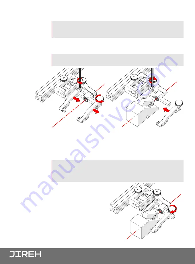
5.
Loosen the probe holder arm adjustment knob
(Fig. 155)
and remove
outer probe holder arm from yoke.
6.
Adjust inner probe holder arm as required to best centre the probe on
the yoke’s pivot axis
(Fig. 155)
.
TIP:
The probe holder yoke can accommodate different probe and wedge
sizes of varying widths. It is best to centre the wedge with the yoke’s
pivot axis to reduce wedge tipping when scanning. Position the inner
probe holder arm accordingly with the centre of the yoke (Fig. 155).
7.
Position the wedge on the
inner probe holder arm
(Fig. 156)
.
8.
Slide outer probe holder arm
along the yoke pinching the
wedge in place.
9.
Tighten probe holder arm
adjustment knob
(Fig. 157)
.
Fig. 155 - Adjust probe holder arms
Fig. 156 - Place wedge
Fig. 157 - Pinch wedge with arm


