SECTION 6 - MAST COMPONENTS
6-16
– JLG Lift –
3121222
Cylinder Rod Assembly - Removal from the Cylinder
Barrel
The following disassembly procedure for removing the
gland end of the cylinder is the same for cylinders 1, 2, and
3.
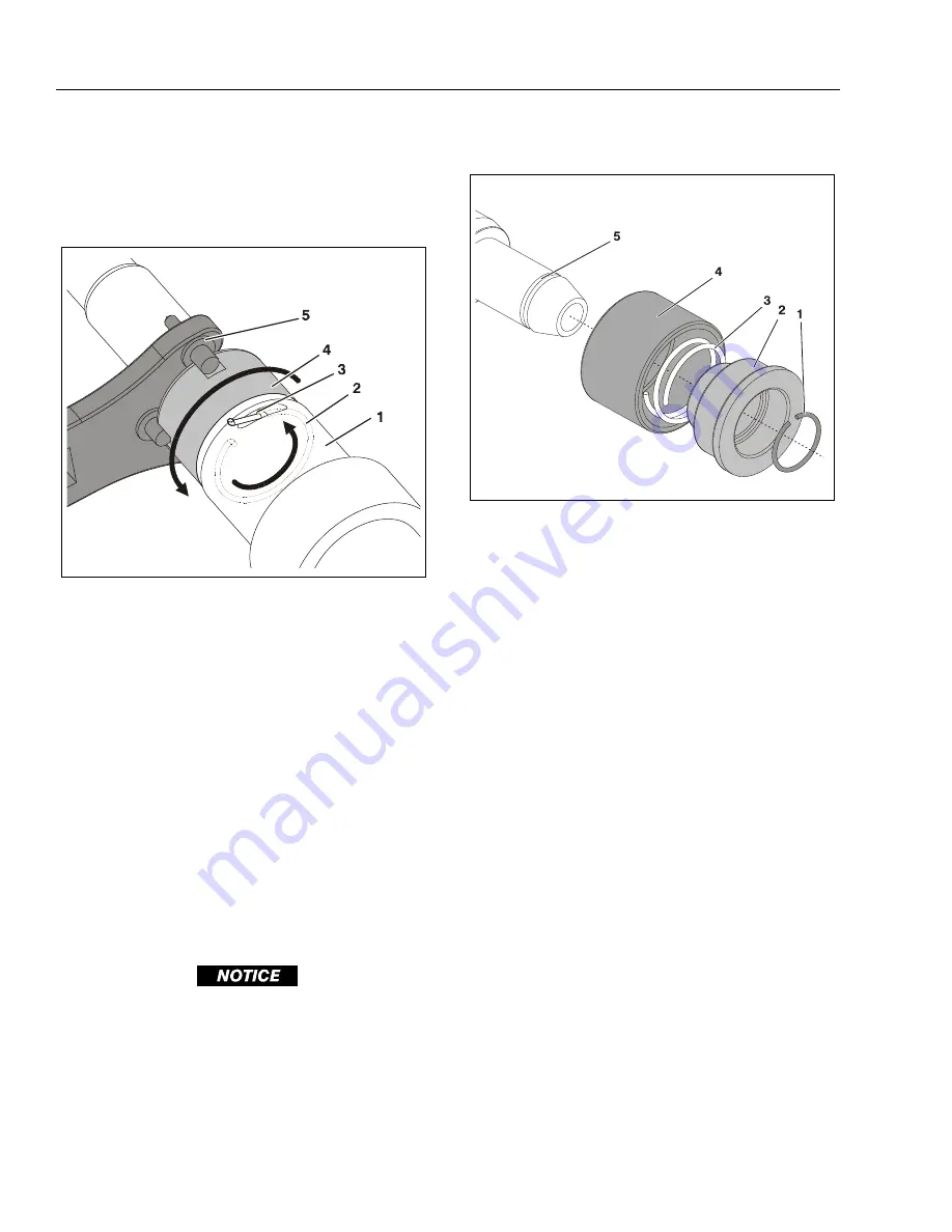
1.
Using pliers and small screwdriver fish the end of
wire retaining ring out of the slot on the gland
end of the cylinder barrel.
2.
Place the spanner wrench pins (48mm - 1.889"
diameter) into the slots in the end of the gland.
3.
Now slowly rotate the gland pulling the gland
retaining ring out of the slot in the side of the
cylinder barrel. Keep rotating gland until the
hood end of the retaining ring is aligned with
the hole in the slot and lift the retaining ring
completely free of the cylinder barrel.
4.
Place a container below the end of the cylinder
barrel and carefully pull the gland out of the end
of the cylinder barrel. Allow any hydraulic oil to
drain.
EXTREME CARE SHOULD BE TAKEN WHEN REMOVING THE CYLINDER
ROD, HEAD, AND PISTON. AVOID PULLING THE ROD OFF CENTER,
WHICH COULD CAUSE DAMAGE TO THE PISTON AND CYLINDER BAR-
REL SURFACES.
5.
Carefully slide the rod assembly out of the cylin-
der barrel and place on a clean surface prefera-
bly a workbench.
Piston - Removal from Cylinder Rod
1.
Remove the piston retaining ring from slot in the
end of the cylinder rod.
2.
Slide piston, compression spring and piston
guide ring off the end of the cylinder rod.
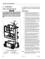
Figure 6-19. Cylinder Rod/Gland - Removal
1.
Cylinder Barrel
2.
Gland Wire Retaining Ring
3.
Retaining Ring Slot/Hole
4.
Cylinder Gland
5.
Spanner Wrench Tool (48mm
- 1.889" Dia.)
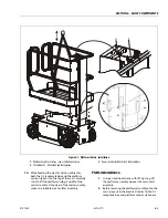
Figure 6-20. Cylinder Rod Piston - Removal
1.
Piston Retaining Ring
2.
Piston
3.
Compression Spring
4.
Piston Guide Ring
5.
Retaining Ring Slot on Cylin-
der Rod
Summary of Contents for 1230ES
Page 1: ...AS NZS Service and Maintenance Manual Model s 1230ES P N 3121222 June 22 2017 ...
Page 2: ...NOTES ...
Page 24: ...SECTION 1 MACHINE SPECIFICATIONS 1 12 JLG Lift 3121222 NOTES ...
Page 32: ...SECTION 2 GENERAL SERVICE INFORMATION 2 8 JLG Lift 3121222 NOTES ...
Page 78: ...SECTION 4 BASE COMPONENTS 4 40 JLG Lift 3121222 NOTES ...
Page 104: ...SECTION 5 CONTROL COMPONENTS 5 26 JLG Lift 3121222 NOTES ...
Page 158: ...SECTION 8 DIAGNOSTIC TROUBLE CODES 8 22 JLG Lift 3121222 NOTES ...
Page 198: ...SECTION 9 GENERAL ELECTRICAL INFORMATION SCHEMATICS 9 40 JLG Lift 3121222 ...
Page 199: ...SECTION 9 GENERAL ELECTRICAL INFORMATION SCHEMATICS 3121222 JLG Lift 9 41 ...
Page 200: ...SECTION 9 GENERAL ELECTRICAL INFORMATION SCHEMATICS 9 42 JLG Lift 3121222 ...
Page 202: ...SECTION 9 GENERAL ELECTRICAL INFORMATION SCHEMATICS 9 44 JLG Lift 3121222 NOTES ...

