SECTION 9 - GENERAL ELECTRICAL INFORMATION & SCHEMATICS
9-8
– JLG Lift –
3121222
Assembly
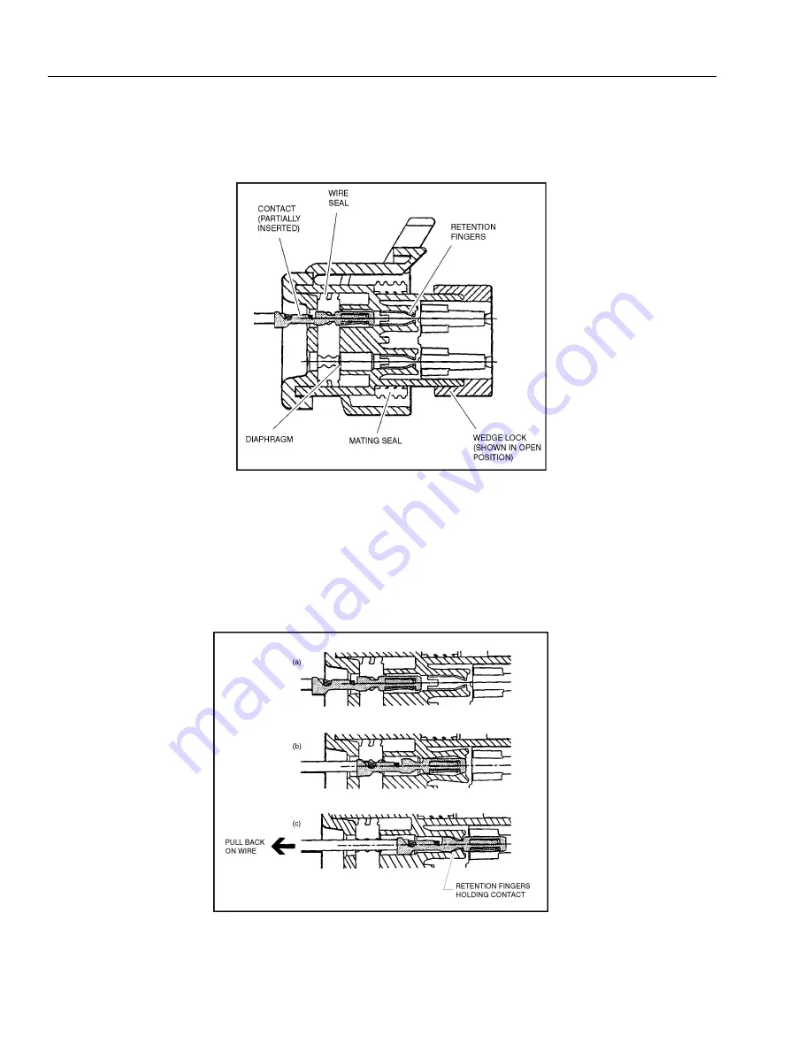
Check to be sure the wedge lock is in the open, or as-shipped, position (See Connector Assembly Figure 1). Proceed as
follows:
Connector Assembly Figure 1
1.
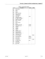
To insert a contact, push it straight into the appropriate circuit cavity as far as it will go (See Connector Assembly Fig-
2.
Pull back on the contact wire with a force of 1 or 2 lbs. to be sure the retention fingers are holding the contact (See
3.
After all required contacts have been inserted, the wedge lock must be closed to its locked position. Release the lock-
ing latches by squeezing them inward (See Connector Assembly Figure 3).
4.
Slide the wedge lock into the housing until it is flush with the housing (See Connector Assembly Figure 4).
Connector Assembly Figure 2
Summary of Contents for 1230ES
Page 1: ...AS NZS Service and Maintenance Manual Model s 1230ES P N 3121222 June 22 2017 ...
Page 2: ...NOTES ...
Page 24: ...SECTION 1 MACHINE SPECIFICATIONS 1 12 JLG Lift 3121222 NOTES ...
Page 32: ...SECTION 2 GENERAL SERVICE INFORMATION 2 8 JLG Lift 3121222 NOTES ...
Page 78: ...SECTION 4 BASE COMPONENTS 4 40 JLG Lift 3121222 NOTES ...
Page 104: ...SECTION 5 CONTROL COMPONENTS 5 26 JLG Lift 3121222 NOTES ...
Page 158: ...SECTION 8 DIAGNOSTIC TROUBLE CODES 8 22 JLG Lift 3121222 NOTES ...
Page 198: ...SECTION 9 GENERAL ELECTRICAL INFORMATION SCHEMATICS 9 40 JLG Lift 3121222 ...
Page 199: ...SECTION 9 GENERAL ELECTRICAL INFORMATION SCHEMATICS 3121222 JLG Lift 9 41 ...
Page 200: ...SECTION 9 GENERAL ELECTRICAL INFORMATION SCHEMATICS 9 42 JLG Lift 3121222 ...
Page 202: ...SECTION 9 GENERAL ELECTRICAL INFORMATION SCHEMATICS 9 44 JLG Lift 3121222 NOTES ...


