SECTION 4 - BASE COMPONENTS
3121222
– JLG Lift –
4-13
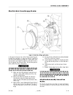
Wheel Drive Brake - Manual Disengage Procedure
In the event of a power loss to the Torque-Hub, the park-
ing brake will engage as a safety precaution. Should the
unit need to be towed or pushed to an area where it can
be serviced or recharged the operator will need to manu-
ally disengage the parking brakes. The following proce-
dure outlines how this is to be done.
IF THE MACHINE IS ON ANY INCLINE, THE WHEELS MUST BE ADE-
QUATELY BLOCKED PRIOR TO MANUALLY DISENGAGING THE BRAKES.
FAILURE TO DO SO MAY RESULT IN INJURY OR EVEN DEATH.
1.
Make sure the E-stop plunger is pushed in and
the key is removed from the key switch on the
Ground Control Station.
2.
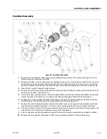
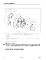
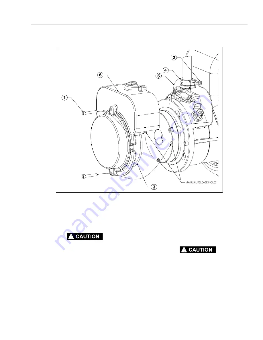
Remove the 2 Back Cover Bolts (
1
). The Back
Cover Bolts are also the release bolts for the
brake. The size of the back cover bolts (
5
) is 0.8 x
20mm long.
3.
Remove the 2 Cover Plate Bolts (
2
) from the front
of the cover area near the cable exit. The size of
the Cover Plate Bolts is (#8 -32UNC x .500 inches
long)
4.
Remove the Cover Plate (
6
), Strain Relief (
4
), Back
Cover (
7
), and Cover O'ring (
3
).
5.
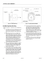
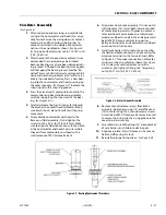
Insert the Back Cover Bolts (
1
) into the two holes
in the brake housing at the 3 and 9 o'clock posi-
tions.
6.
Tighten down bolts and the brake will disen-
gage.
7.
Repeat this procedure for the other wheel drive.
THE DISENGAGE BOLTS MUST BE REMOVED FROM THE BRAKE HOUS-
ING AFTER THE MACHINE IS TOWED OR PUSHED TO ITS SERVICING
LOCATION. THE BRAKES CAN NOT BE ENGAGED WITH THE DISENGAGE
BOLTS IN THE BRAKE HOUSING. THIS WILL CAUSE THE MACHINE TO
ROLL WHEN PARKED ON AN INCLINE.
Wheel Drive Motor Assembly - Removal From
Machine
The electric wheel drive assemblies are mounted indepen-
tent of each other on the base frame at the front of the
machine.
Figure 4-4. Brake Manual Disengage Procedure
Summary of Contents for 1230ES
Page 1: ...AS NZS Service and Maintenance Manual Model s 1230ES P N 3121222 June 22 2017 ...
Page 2: ...NOTES ...
Page 24: ...SECTION 1 MACHINE SPECIFICATIONS 1 12 JLG Lift 3121222 NOTES ...
Page 32: ...SECTION 2 GENERAL SERVICE INFORMATION 2 8 JLG Lift 3121222 NOTES ...
Page 78: ...SECTION 4 BASE COMPONENTS 4 40 JLG Lift 3121222 NOTES ...
Page 104: ...SECTION 5 CONTROL COMPONENTS 5 26 JLG Lift 3121222 NOTES ...
Page 158: ...SECTION 8 DIAGNOSTIC TROUBLE CODES 8 22 JLG Lift 3121222 NOTES ...
Page 198: ...SECTION 9 GENERAL ELECTRICAL INFORMATION SCHEMATICS 9 40 JLG Lift 3121222 ...
Page 199: ...SECTION 9 GENERAL ELECTRICAL INFORMATION SCHEMATICS 3121222 JLG Lift 9 41 ...
Page 200: ...SECTION 9 GENERAL ELECTRICAL INFORMATION SCHEMATICS 9 42 JLG Lift 3121222 ...
Page 202: ...SECTION 9 GENERAL ELECTRICAL INFORMATION SCHEMATICS 9 44 JLG Lift 3121222 NOTES ...


