SECTION 4 - BASE COMPONENTS
3121222
– JLG Lift –
4-25
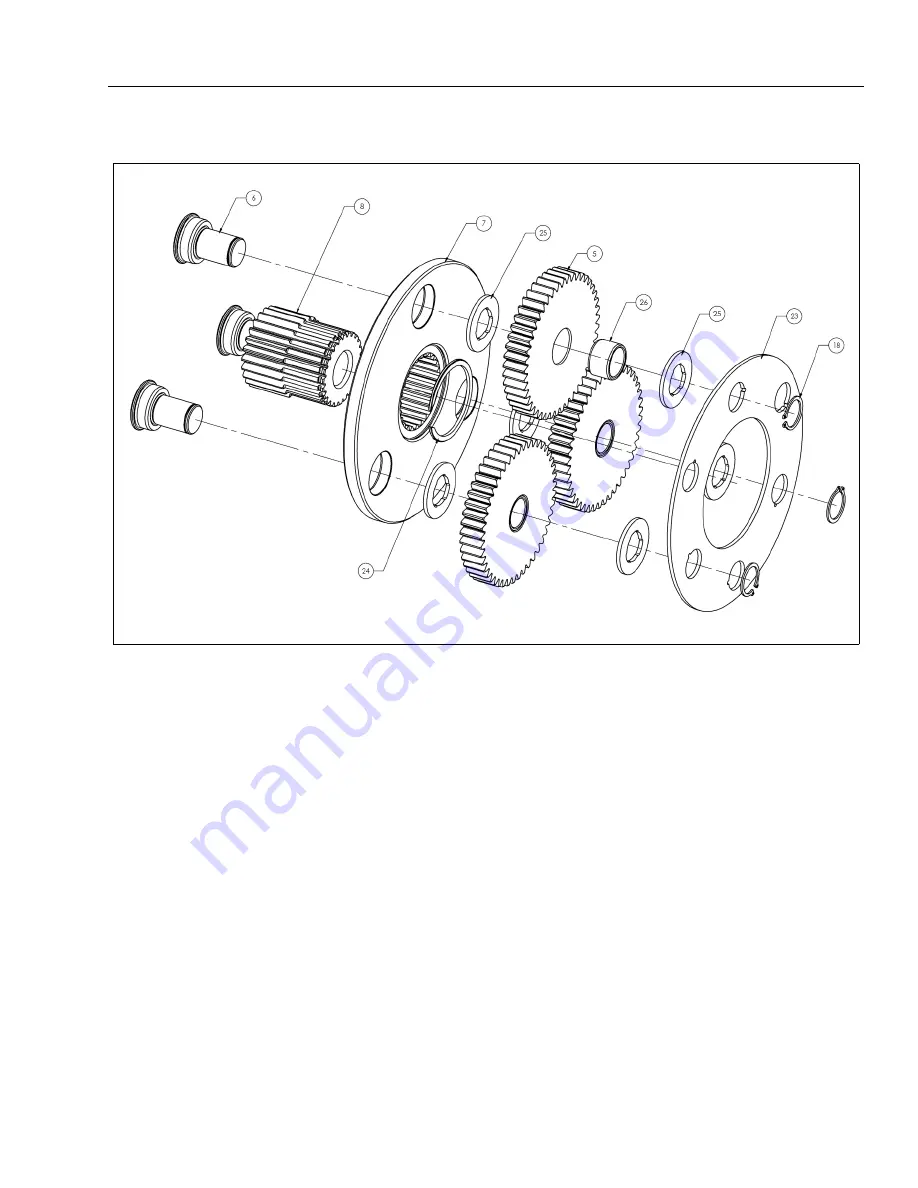
Input Carrier Sub-Assembly
Input Carrier Sub-Assembly
1.
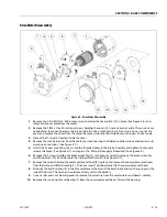
Use the Input Planet Shaft (6) as a pressing tool to install the Planet Bushing (26) into the bore of each Planet
Gear (5). The shaft will help guide the bushing into the bore as well as prevent damage from the press.
2.
Press three Input Planet Shafts (6) into the three holes of the Input Carrier (7). The head of the Input Planet
Shaft (6) needs to sit flush in the counterbore of the Input Carrier (7) hole
3.
Insert Output Sun Gear (8) into the splined bore of the Input Carrier (7). The gear tooth end of the Output
Sun Gear (8) should protrude in the opposite direction of the Input Planet Shafts (6).
4.
Using retaining ring pliers, install the Retaining Ring (24) into the groove of the Output Sun Gear (8). Make
sure that the Retaining Ring (24) is correctly seated in the groove and that the Output Sun Gear (8) cannot
be pulled out of the Input Carrier (7).
5.
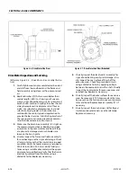
Place a Thrust Washer (25) on each side of the Input Planet Gear (5). Line up the bores as well as you can
visually. Additional grease may help hold everything together.
6.
Place the Input Planet Gear (5) and Thrust Washers (25) onto the Input Planet Shaft (6) sticking out from the
Input Carrier (7).
7.
Repeat 5 & 6 for the other 2 Planet Gears.
8.
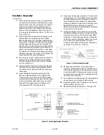
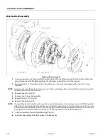
Put the Thrust Plate (23) onto the three Input Planet Shafts (6). Use the three holes on the innermost bolt cir-
cle. The other three holes are for a different gear ratio.
9.
Using the appropriate retaining ring pliers put a Retaining Ring (18) into the groove of each Input Planet
Shaft (6).
NOTE:
Do not overstress the Retaining Rings (18).
Summary of Contents for 1230ES
Page 1: ...AS NZS Service and Maintenance Manual Model s 1230ES P N 3121222 June 22 2017 ...
Page 2: ...NOTES ...
Page 24: ...SECTION 1 MACHINE SPECIFICATIONS 1 12 JLG Lift 3121222 NOTES ...
Page 32: ...SECTION 2 GENERAL SERVICE INFORMATION 2 8 JLG Lift 3121222 NOTES ...
Page 78: ...SECTION 4 BASE COMPONENTS 4 40 JLG Lift 3121222 NOTES ...
Page 104: ...SECTION 5 CONTROL COMPONENTS 5 26 JLG Lift 3121222 NOTES ...
Page 158: ...SECTION 8 DIAGNOSTIC TROUBLE CODES 8 22 JLG Lift 3121222 NOTES ...
Page 198: ...SECTION 9 GENERAL ELECTRICAL INFORMATION SCHEMATICS 9 40 JLG Lift 3121222 ...
Page 199: ...SECTION 9 GENERAL ELECTRICAL INFORMATION SCHEMATICS 3121222 JLG Lift 9 41 ...
Page 200: ...SECTION 9 GENERAL ELECTRICAL INFORMATION SCHEMATICS 9 42 JLG Lift 3121222 ...
Page 202: ...SECTION 9 GENERAL ELECTRICAL INFORMATION SCHEMATICS 9 44 JLG Lift 3121222 NOTES ...

