SECTION 5 - CONTROL COMPONENTS
3121222
– JLG Lift –
5-17
5.7
PLATFORM CONTROL STATION - SERVICE INFORMATION
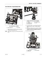
Platform Control Station Assembly
Upper Control Box - Component Replacement
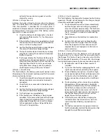
1.
Disconnect the platform control box and remove
from the machine.
2.
Place the platform control box on a suitable
work bench.
3.
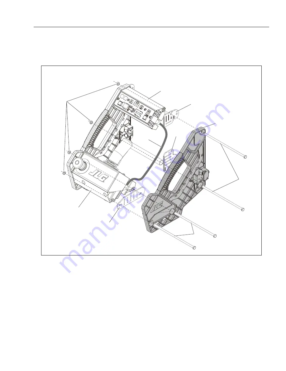
Loosen and remove the long through bolts that
hold the two side control housings together.
NOTE:
You may have to only loosen the two power bolts
and remove the two closest the top in order to get to
the printed circuit board located in the top of the
control box where the drive/lift select switch is
located.
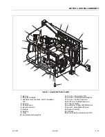
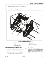
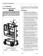
Figure 5-7. Platform Control Station Assembly
1.
Assembly Bolts
2.
Nuts
3.
Side Panel
4.
Mounting/Reinforcement Plates
5.
Upper Control Box
6.
Lower Control Box
7.
Upper Control Box Wiring Harness
1
2
3
4
5
6
4
7
4
1
Summary of Contents for 1230ES
Page 1: ...AS NZS Service and Maintenance Manual Model s 1230ES P N 3121222 June 22 2017 ...
Page 2: ...NOTES ...
Page 24: ...SECTION 1 MACHINE SPECIFICATIONS 1 12 JLG Lift 3121222 NOTES ...
Page 32: ...SECTION 2 GENERAL SERVICE INFORMATION 2 8 JLG Lift 3121222 NOTES ...
Page 78: ...SECTION 4 BASE COMPONENTS 4 40 JLG Lift 3121222 NOTES ...
Page 104: ...SECTION 5 CONTROL COMPONENTS 5 26 JLG Lift 3121222 NOTES ...
Page 158: ...SECTION 8 DIAGNOSTIC TROUBLE CODES 8 22 JLG Lift 3121222 NOTES ...
Page 198: ...SECTION 9 GENERAL ELECTRICAL INFORMATION SCHEMATICS 9 40 JLG Lift 3121222 ...
Page 199: ...SECTION 9 GENERAL ELECTRICAL INFORMATION SCHEMATICS 3121222 JLG Lift 9 41 ...
Page 200: ...SECTION 9 GENERAL ELECTRICAL INFORMATION SCHEMATICS 9 42 JLG Lift 3121222 ...
Page 202: ...SECTION 9 GENERAL ELECTRICAL INFORMATION SCHEMATICS 9 44 JLG Lift 3121222 NOTES ...


