SECTION 3 - CHASSIS & TURNTABLE
3-32
3121619
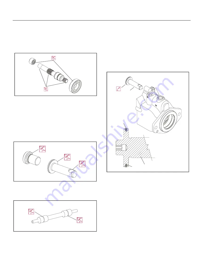
SHAFT BEARINGS
Inspect bearings for excessive wear or contamination. Rotate
bearings while feeling for uneven movement. Bearings should
spin smoothly and freely. Replace bearings that appear worn
or do not rotate smoothly.
SHAFT
Inspect motor shaft for damage or excessive wear on output
and block splines. Inspect bearing surfaces and sealing sur-
face. Replace shafts with damaged or excessively worn splines,
bearing surfaces, or sealing surfaces.
SERVO PISTON AND MINIMUM ANGLE STOP
Inspect minimum angle stop, servo piston head, and servo pis-
ton ball-socket for damage or excessive wear. Replace as
required.
LOOP FLUSHING SPOOL
Inspect loop flushing spool for cracks or damage. Replace as
required.
Assembly
1.
Install new O-ring (1) and piston seal (2) to servo piston
(3). Install piston seal over O-ring.
NOTE:
Installing piston seal stretches it, making it difficult to
install servo piston in its bore. Allow 30 minutes for seal to
relax after installation. To speed up seal relaxation, com-
press seal by installing piston head in end-cap servo cavity
and let it stand for at least five minutes.
Figure 3-27. Servo Piston
2.
After piston seal has relaxed, lubricate and install servo
piston in housing bore. Align piston with ball socket fac-
ing inside of housing.
1.
O-ring
2.
Piston Seal
3.
Servo Piston
2
1
3
3
Summary of Contents for 1850SJ
Page 1: ...Service and Maintenance Manual Model 1850SJ 3121619 June 29 2018 Rev J AS NZS...
Page 2: ......
Page 21: ...3121619 xvii LIST OF FIGURES FIGURE NO TITLE PAGE NO Thispageleftblankintentionally...
Page 24: ...xx 3121619 LIST OF TABLES TABLE NO TITLE PAGE NO Thispageleftblankintentionally...
Page 50: ...SECTION 2 GENERAL 2 12 3121619 NOTES...
Page 55: ...SECTION 3 CHASSIS TURNTABLE 3121619 3 5 This page left blank intentionally...
Page 56: ...SECTION 3 CHASSIS TURNTABLE 3 6 3121619 Figure 3 4 Axle Hose Routing Sheet 1 of 2...
Page 57: ...SECTION 3 CHASSIS TURNTABLE 3121619 3 7 Figure 3 5 Axle Hose Routing Sheet 2 of 2...
Page 58: ...SECTION 3 CHASSIS TURNTABLE 3 8 3121619 Figure 3 6 Steering Axle Hydraulic Circuit...
Page 61: ...SECTION 3 CHASSIS TURNTABLE 3121619 3 11 Figure 3 9 Turntable Hydraulic System...
Page 92: ...SECTION 3 CHASSIS TURNTABLE 3 42 3121619 Figure 3 39 Swing Bearing Wear Tolerance...
Page 94: ...SECTION 3 CHASSIS TURNTABLE 3 44 3121619 Figure 3 41 Swing Bearing Removal Sheet 2 of 4...
Page 110: ...SECTION 3 CHASSIS TURNTABLE 3 60 3121619 Figure 3 54 Engine Electrical Circuit...
Page 169: ...SECTION 4 BOOM PLATFORM 3121619 4 7 Figure 4 1 Boom Hydraulic System...
Page 173: ...SECTION 4 BOOM PLATFORM 3121619 4 11 Figure 4 2 Boom Assembly Sheet 1 of 9...
Page 174: ...SECTION 4 BOOM PLATFORM 4 12 3121619 Figure 4 3 Boom Assembly Sheet 2 of 9...
Page 175: ...SECTION 4 BOOM PLATFORM 3121619 4 13 Figure 4 4 Boom Assembly Sheet 3 of 9...
Page 176: ...SECTION 4 BOOM PLATFORM 4 14 3121619 Figure 4 5 Boom Assembly Sheet 4 of 9...
Page 177: ...SECTION 4 BOOM PLATFORM 3121619 4 15 Figure 4 6 Boom Assembly Sheet 5 of 9...
Page 178: ...SECTION 4 BOOM PLATFORM 4 16 3121619 Figure 4 7 Boom Assembly Sheet 6 of 9...
Page 179: ...SECTION 4 BOOM PLATFORM 3121619 4 17 Figure 4 8 Boom Assembly Sheet 7 of 9...
Page 180: ...SECTION 4 BOOM PLATFORM 4 18 3121619 Figure 4 9 Boom Assembly Sheet 8 of 9...
Page 181: ...SECTION 4 BOOM PLATFORM 3121619 4 19 Figure 4 10 Boom Assembly Sheet 9 of 9...
Page 187: ...SECTION 4 BOOM PLATFORM 3121619 4 25 Figure 4 16 Boom Assembly Torque Values Sheet 1 of 4...
Page 188: ...SECTION 4 BOOM PLATFORM 4 26 3121619 Figure 4 17 Boom Assembly Torque Values Sheet 2 of 4...
Page 189: ...SECTION 4 BOOM PLATFORM 3121619 4 27 Figure 4 18 Boom Assembly Torque Values Sheet 3 of 4...
Page 190: ...SECTION 4 BOOM PLATFORM 4 28 3121619 Figure 4 19 Boom Assembly Torque Values Sheet 4 of 4...
Page 201: ...SECTION 4 BOOM PLATFORM 3121619 4 39 Figure 4 20 Hose Adjustment...
Page 202: ...SECTION 4 BOOM PLATFORM 4 40 3121619 Figure 4 21 Section 3 Boom Cables...
Page 203: ...SECTION 4 BOOM PLATFORM 3121619 4 41 Figure 4 22 Section 4 Boom Cables...
Page 204: ...SECTION 4 BOOM PLATFORM 4 42 3121619 Figure 4 23 Section 5 Boom Cables...
Page 205: ...SECTION 4 BOOM PLATFORM 3121619 4 43 Figure 4 24 Jib Hydraulics Sheet 1 of 7...
Page 234: ...SECTION 4 BOOM PLATFORM 4 72 3121619 Figure 4 44 Powertrack Shimming Instructions...
Page 239: ...SECTION 4 BOOM PLATFORM 3121619 4 77 Figure 4 49 Powertrack Hose Installation Sheet 1 of 4...
Page 240: ...SECTION 4 BOOM PLATFORM 4 78 3121619 Figure 4 50 Powertrack Hose Installation Sheet 2 of 4...
Page 241: ...SECTION 4 BOOM PLATFORM 3121619 4 79 Figure 4 51 Powertrack Hose Installation Sheet 3 of 4...
Page 242: ...SECTION 4 BOOM PLATFORM 4 80 3121619 Figure 4 52 Powertrack Hose Installation Sheet 4 of 4...
Page 252: ...SECTION 4 BOOM PLATFORM 4 90 3121619 NOTES...
Page 432: ...SECTION 5 BASIC HYDRAULIC INFORMATION HYDRAULIC SCHEMATICS 5 180 3121619 NOTES...
Page 527: ...SECTION 6 JLG CONTROL SYSTEM 3121619 6 95 Figure 6 36 LSS Installation Sheet 1 of 4...
Page 528: ...SECTION 6 JLG CONTROL SYSTEM 6 96 3121619 Figure 6 37 LSS Installation Sheet 2 of 4...
Page 529: ...SECTION 6 JLG CONTROL SYSTEM 3121619 6 97 Figure 6 38 LSS Installation Sheet 3 of 4...
Page 530: ...SECTION 6 JLG CONTROL SYSTEM 6 98 3121619 Figure 6 39 LSS Installation Sheet 4 of 4...
Page 710: ...SECTION 7 BASIC ELECTRICAL INFORMATION ELECTRICAL SCHEMATICS 7 118 3121619 NOTES...
Page 711: ......


