SECTION 3 - CHASSIS & SCISSOR ARMS
3121273
– JLG Lift –
3-19
3.13 DRIVE MOTOR SERVICING
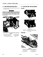
The drive motors are located at the rear of the machine,
inside the machine rear cover, remove the machine rear
cover, see Figure 3-1.
Drive Motor Troubleshooting
1. Turn off power to unit, remove side cover and dis-
connect main battery power.
2. Disconnect drive motor connections from the Power
Module inside rear cover.
3. Verify field continuity between the blue and orange
wires. If available, use a 4-wire ohmmeter to verify
the field resistance per the applicable motor specifi-
cation below.
4. Verify armature continuity between the red and black
wires. If available, use a 4-wire ohmmeter to verify
the field resistance per the applicable motor specifi-
cation below.
5. Using a dielectric tester, verify that there are no
shorts between the following items:
a. Field connector pins and the case of the motor.
b. Armature terminals and the case of the motor.
c. Field connector pins to the armature terminals.
6. Verify continuity in 2 pin brake connector (yellow
and brown wires). Measure the brake resistance and
verify that it is between 18 and 22 Ohms.
Drive Motor Electrical Evaluation
Several basic electrical tests can be performed on the
Drive Motors. Failure of one of these evaluations is signifi-
cant and may indicate that the device is physically dam-
aged.
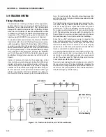
Refer to Figure 7-2., Resistance Measurement. Disconnect
the Main Battery Disconnect and all drive motor cables
during this analysis.
•
Resistance < 2 Ohms Red to Black Armature Wires.
The heavy red and black conductors are connected to
the motor's armature winding. The winding is a very low
impedance and should appear to be a short-circuit for
an ordinary voltmeter. High resistance can signal corro-
sion, improper crimps, damaged cabling, worn
brushes, a faulty commutator, or an open armature
winding.
•
Resistance < 2 Ohms Blue to Orange Field Wires.
The blue and orange conductors are connected to the
motor's field winding. In order to make this measure-
ment, it will be necessary to disconnect the butt-splice
on the two orange wires or use a piercing meter probe.
As with the armature, the field is a very low impedance
and should appear to be a short-circuit for an ordinary
voltmeter. High resistance can signal corrosion,
improper crimps, damaged connectors, damaged
cabling, or an open field winding.
•
Resistance 15-25 Ohms Yellow to Brown Brake
Wires.
The yellow and brown wires are connected to
the integral brake. Improper resistance can signal cor-
rosion, improper crimps, damaged cabling, or a faulty
solenoid.
•
Resistance > 1 Mega-Ohms Red Armature Wire to
Motor Housing.
The armature winding should be elec-
trically isolated from the motor housing. Low resistance
may be an indication of a crushed cable, a burned
cable, or a burned armature winding. Investigate by dis-
connecting the drive motor cable from the motor and
re-measure resistance (isolation).
•
Resistance > 1 Mega-Ohms Blue Field Wire to
Motor Housing.
The field winding should also be elec-
trically isolated from the motor housing. Low resistance
may be an indication of a crushed cable, a burned
cable, or a burned field winding. Investigate by discon-
necting the drive motor cable from the motor and re-
measure resistance (isolation).
•
Resistance > 1 Mega-Ohms Red Armature Wire to
Blue Field Wire.
The armature and field windings
should also be electrically isolated from one another.
Low resistance may be an indication of a crushed
cable, a burned cable, damaged windings. Investigate
by disconnecting the drive motor cable from the motor
and re-measure resistance (isolation).
Servicing Guidelines
Since the operating environment of industrial equipment
varies widely, the following are suggested for periodic
maintenance inspection intervals.
•
Normal Service
– Perform routine inspection (outlined
in the Inspection and Service portion of this section)
every 1,000 hours of drive time.
•
Severe Service
– Perform routine inspection every 500
hours of drive time. Severe service environments are
listed below:
a. Dusty or dirty locations like cement plants, lum-
ber and flour mills, coal mining, stone quarries,
etc.
b. High temperature areas like steel mills, found-
ries, etc.
c. Environments with sudden temperature change,
such as in refrigeration plant, etc.
Model
Field Resistance
@ 75°F (24°C)
Armature Resistance
@ 75°F (24°C)
1932RS/6RS
0.21 Ohms
0.037 Ohms
3248RS/10RS
0.127 Ohms
0.051 Ohms


