SECTION 3 - CHASSIS & SCISSOR ARMS
3-22
– JLG Lift –
3121273
Drive Motor Disassembly
NOTE:
Refer to Figure 3-24.
1. Remove the two Cover Plate Mounting Screws (14)
holding the Cover Plate (13) in place and remove the
cover plate from the motor.
2. Remove the Brake Cover Mounting Screws (15)
holding the Brake (11) in place and set aside. These
screws are used to manually release the brakes.
3. Remove the two Terminal Cover Mounting Screws
(16). Slide the strain relief of the Wire Harness (1)
out of the cover and remove the cover from the
motor.
4. Discard the Gasket (12) that was located under the
brake and terminal covers.
5. Remove the wire harness from the motor by discon-
necting the brake connection and armature connec-
tions. Cut the field connection close to the crimp
connection on the motor side.
6. Install the two Brake Cover Mounting Screws (15)
into the threaded holes in the brake assembly and
tighten to manually release the brake (see Figure 3-
23.).
7. Remove the three screws holding the brake assem-
bly to the motor. Carefully remove the brake assem-
bly, brake disc and reaction disc from the motor by
sliding off of the shaft.
8. Remove the screws holding the Commutator End
Head (9) in place and remove the commutator end
head from the frame and field assembly. The Arma-
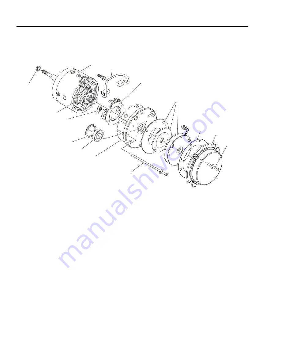
Figure 3-24. Drive Motor Components
1.
Shaft Pilot Bearing
2.
Frame & Field Assembly
3.
Armature Assembly
4.
Brush Spring (4)
5.
Brush & Terminal Assembly (Qty.-2)
6.
Brush Box Assembly
7.
Retaining Ring
8.
Bearing
9.
Commutator End Head
10.
Motor to Hub Mounting Screws (Qty.-2)
11.
Brake Assembly
12.
Cover Gasket
13.
Brake Cover
14.
Brake Cover Mounting Screws (Qty.-2)
2
3
4
5
6
7
8
9
11
10
14
1
13
12


