SECTION 5 - JLG CONTROL SYSTEM
3121788
5-1
SECTION 5. JLG CONTROL SYSTEM
5.1
HAND HELD ANALYZER
Diagnostic Port
To connect the Hand Held Analyzer, the diagnostic port
plug
(1)
is located in chassis harness close to the
hydraulic valve manifold
(2)
, and machine controller
logic module
(3),
inside the right side compartment
door, as shown in Figure 5-2.
To Connect the Hand Held Analyzer:
1.
Connect the four pin end of the cable supplied
with the analyzer, to the diagnostic port plug
and connect the remaining end of the cable to
the analyzer.
NOTE:
The cable has a four pin connector at each end of
the cable; the cable cannot be connected back-
wards.
2.
Power up the control system by turning the
ground control station - platform/ground selec-
tor switch - to the platform position and pulling
both platform and ground control emergency
stop buttons on.
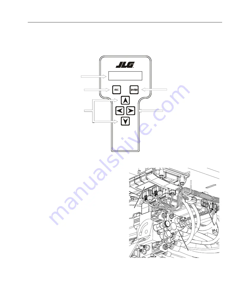
Figure 5-1. Hand Held Analyzer
men u:
PRESS ENTER
HELP:
Analyzer Display
Escape Key
To return home or access previ-
ous menu
Enter Key
Stores and selects Top Level, Sub Level,
and item menus
Left & Right Arrow Keys
Used to move between Top Level, Sub
Level, and item menus
Up & Down Arrow Keys
Value Selector
MAF10120
Figure 5-2. Diagnostic Port Location
(Inside right side compartment door)
1.
Diagnostic Port Plug
2.
Hydraulic Valve Manifold
3.
Controller
Logic Module
3
2
1
Go to
Discount-Equipment.com
to
order your
parts


