SECTION 3 - CHASSIS, PLATFORM, & SCISSOR ARMS
3-62
31215079
Generator (If Equipped)
ALLOW ENGINE AND COMPONENTS TO COOL DOWN BEFORE SERVIC-
ING.
REMOVAL
1. Disable machine operation. Rotate engine tray to
access back of engine.
2. Disconnect and label electrical wires attached to
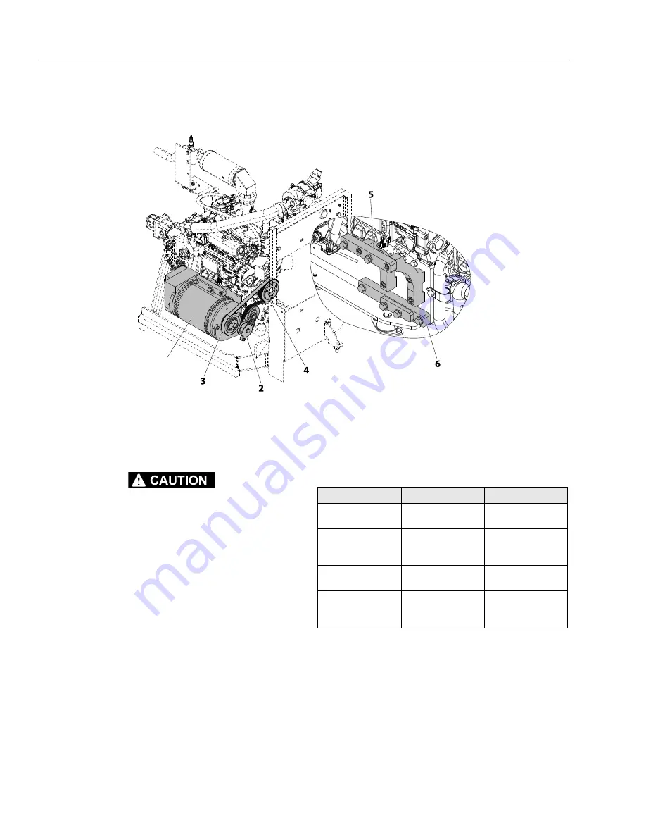
generator (1).
3. Remove drive belt tension using the belt tensioner
and remove belt from generator pulley.
4. Remove the generator from the engine by removing
the two upper bracket (5) bolts, nuts, and washers.
And the lower pivot, belt tensioner bolt, nut, and
washer.
5. Replace belt if damaged.
INSTALLATION
1. Follow Removal Steps in reverse. Ensure belt is tight
before securing generator with the bolts.
NOTE:
Apply Medium Strength Threadlocking Compound
to the threads of the generator mounting bolts.
NOTE:
The generator control box is mounted on the rear
wall of the Hydraulic/Fuel Tank cabinet just behind
the ground control station.
The platform junction box is mounted under the
platform deck on the Hydraulic/Fuel Tank cabinet
side of the machine.
See Section 6, Electrical Schematics generator elec-
trical configuration.
1. Generator
2. Belt Tensioner
3. Drive Belt
4. Drive Pulley
5. Upper Bracket Assembly
6. Lower Bracket
Figure 3-52. AC Generator Installation
1
Table 3-11. AC Generator Specifications
DESCRIPTION
7500 KW
4500 KW
Voltage
120/240V AC
120/240 V AC - 60Hz
110/230V AC - 50Hz
Continuous
7.5 KW - 240V - 3 Phase
6.0 KW - 240V - 1 Phase
6.0 KW - 120V - 1 Phase
4.0 KW - 1 Phase
Peak
8.5 KW - 3 Phase
6.0 KW - 1 Phase
4.0 KW
Amps Peak
18.3 Amps - 3 Phase
26 Amps - 1 Phase
50 Amps - 1 Phase
20 Amps
Go
to
Discount-Equipment.com
to
order
your
parts


