SECTION 3 - CHASSIS, PLATFORM, & SCISSOR ARMS
3-74
31215079
Adjustment of The Actuator
ADJUSTMENT OF THE ACTUATOR PROCEDURE
1. Adjust the nuts at the clevis connection or at the eye
bolt connection to maintain the proper air gap
between the throttle arm and the high idle stop, if
necessary.
NOTE:
Make sure that the plunger rod does not rub the eye-
bolt.
2. Make sure that the linkage and clevis is correctly
adjusted before tightening of linkage assembly.
3. Use lockwasher and jam nut to tighten the linkage
assembly.
MAF15590
7****
6***
2
1
4**
3*
8
5***
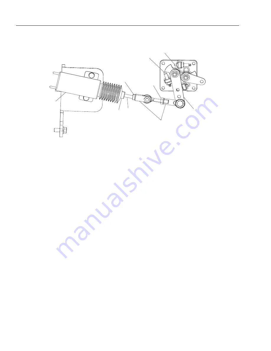
1. Clevis Adjustment Connection
2. Eyebolt Adjustment Connection
3. Actuator Plunger
4. Plunger Rod
5. Low Idle Stop
6. High Idle Stop
7. Throttle Lever
8. Throttle Actuator
Figure 3-64. Adjustment of the Actuator
* Do not use flats on plunger to tighten linkage.
** Do not attempt to adjust rod to plunger connection.
*** Do not tamper or adjust the low and high idle settings.
**** Do not reposition the throttle lever.
1. Clevis Adjustment Connection
2. Eyebolt Adjustment Connection
3. Actuator Plunger
4. Plunger Rod
5. Low Idle Stop
6. High Idle Stop
7. Throttle Lever
8. Throttle Actuator
Figure 3-64. Adjustment of the Actuator
BACKUP WRENCH LOCATIONS
Go to
Discount-Equipment.com
to
order your
parts


