SECTION 3 - CHASSIS & SCISSOR ARMS
3-70
– JLG Sizzor –
3121133
4.
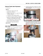
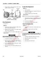
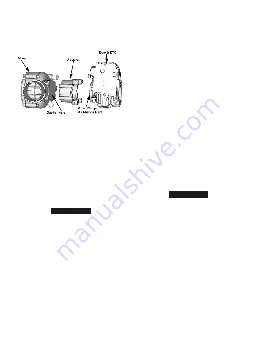
Place gasket on intake manifold and attach mixer/
throttle assembly to manifold.
Mixer Replacement
REMOVAL
1.
Remove the Throttle control device Refer to Elec-
tronic Throttle Body Replacement.
2.
Remove the four (4) bolts to the throttle control
device to mixer adapter bolts.
3.
Remove and discard the mixer to adapter gasket.
INSTALLATION
NOTICE
COVER THROTTLE BODY ADAPTER OPENING TO PREVENT
DEBRIS FROM ENTERING ENGINE UNTIL REASSEMBLY.
1.
Install Mixer to adapter gasket onto the mixer.
2.
Install the mixer to the throttle control device to
mixer adapter and secure with the 4 retaining
screws. Tighten 80 lb-in (9 Nm).
3.
Install Throttle body. Refer to Electronic Throttle
Control Device Replacement.
4.
Start the engine and leak check all fittings and con-
nections.
Coolant Hose Replacement
REMOVAL
1.
Drain the coolant.
2.
Using hose clamp pliers, disconnect both hose
clamps on each hose.
3.
Remove the hose from each of the fittings.
INSTALLATION
NOTE:
Use hose material and lengths specified by JLG.
1.
Install the hose clamps to each hose and set the
clamp back on each hose to make installation eas-
ier.
2.
Fit the hose to the fittings.
3.
Secure by positioning each of the clamps.
Vapor Hose Replacement
REMOVAL
1.
Using hose clamp pliers disconnect both hose
clamps.
2.
Remove the vapor hose from each fitting.
INSTALLATION
NOTICE
THE VAPOR SUPPLY HOSE IS SPECIFICALLY DESIGNED, DO
NOT USE HOSE MATERIAL OR LENGTH OTHER THAN JLG SPEC-
IFIED PARTS.
1.
Install hose clamps and set back on each hose.
2.
Reinstall the vapor hose to each fitting.
3.
Reset clamps.
4.
Start engine and check for leaks.
Figure 3-41. Mixer Assembly
Property of American Airlines

