SECTION 3 - CHASSIS & TURNTABLE
3-66
– JLG Lift –
3121290
3.11 DEUTZ EMR 2
The EMR2 system consists of sensors, control unit, and an actu-
ator. Engine-side controls and the JLG Control System are con-
nected by separate cable harnesses to the EMR control unit.
Engine sensors provide control unit electronics with informa-
tion of the current condition of engine and preconditions
(throttle position etc.). The EMR2 controls an actuator that
operates the injection pump control rod and adjusts fuel
quantity to meet performance requirements.
Regulating rod position is reported back and corrected by the
control rod travel sensor, situated together with rotation mag-
nets in the actuator housing.
The EMR2 is equipped with safety devices and measures in the
hardware and software for emergency running (Limp home)
functions.
To switch engine off, the EMR2 is switched in a de-energized
fashion over the ignition switch. A strong spring in the actua-
tor presses the control rod in the de-energized condition to
the zero position. As a redundancy measure, an additional
solenoid serves for switching off and this, independently of
the actuator, also moves the control rod in the de-energized
condition into the zero position.
After programming over the ISO9141 interface, the EMR2 pos-
sesses a motor-specific data set matched by engine serial
number. Modules cannot be swapped between engines.
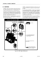
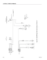
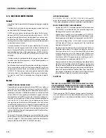
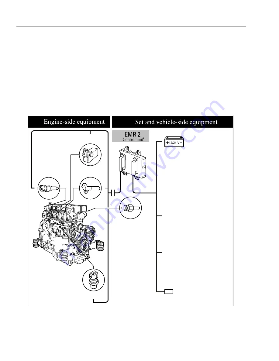
Figure 3-46. EMR 2 Engine Side Equipment
GLOW PLUG
POWER SUPPLY
COOLANT TEMPERATURE
SENSOR
CONTROL ROD POSITION
SENSOR/ACTUATOR
CAMSHAFT
SPEED
OIL PRESSURE
SENSOR
JLG SYSTEM USES JLG ANALYZER TO
REPORT FAULTS
DIAGNOSIS INTERFACE/CAN-BUS;
JLG SYSTEM USES THIS TO CONTROL
ENGINE & FAULT REPORTING.
JLG SYSTEM HANDLES ENGINE START/
STOP; EMR2 TAKES CONTROL OF THE
ENGINE AT 700RPM
Summary of Contents for 450A II Series
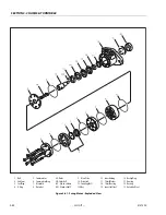
Page 46: ...SECTION 3 CHASSIS TURNTABLE 3 6 JLG Lift 3121290 Figure 3 4 Drive Hub 4WD Front Only ...
Page 79: ...SECTION 3 CHASSIS TURNTABLE 3121290 JLG Lift 3 39 Figure 3 32 Swing Bearing Drive ...
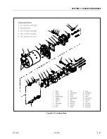
Page 101: ...SECTION 3 CHASSIS TURNTABLE 3121290 JLG Lift 3 61 Figure 3 42 Auxiliary Pump ...
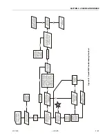
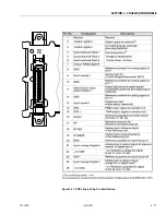
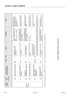
Page 113: ...SECTION 3 CHASSIS TURNTABLE 3121290 JLG Lift 3 73 Figure 3 53 EMR2 Fault Codes Sheet 1 of 5 ...
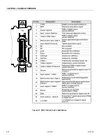
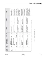
Page 114: ...SECTION 3 CHASSIS TURNTABLE 3 74 JLG Lift 3121290 Figure 3 54 EMR2 Fault Codes Sheet 2 of 5 ...
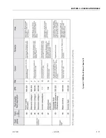
Page 115: ...SECTION 3 CHASSIS TURNTABLE 3121290 JLG Lift 3 75 Figure 3 55 EMR2 Fault Codes Sheet 3 of 5 ...
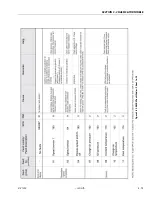
Page 116: ...SECTION 3 CHASSIS TURNTABLE 3 76 JLG Lift 3121290 Figure 3 56 EMR2 Fault Codes Sheet 4 of 5 ...
Page 117: ...SECTION 3 CHASSIS TURNTABLE 3121290 JLG Lift 3 77 Figure 3 57 EMR2 Fault Codes Sheet 5 of 5 ...
Page 159: ...SECTION 3 CHASSIS TURNTABLE 3121290 JLG Lift 3 119 ...
Page 161: ...SECTION 3 CHASSIS TURNTABLE 3121290 JLG Lift 3 121 ...
Page 163: ...SECTION 3 CHASSIS TURNTABLE 3121290 JLG Lift 3 123 ...
Page 165: ...SECTION 3 CHASSIS TURNTABLE 3121290 JLG Lift 3 125 ...
Page 173: ...SECTION 3 CHASSIS TURNTABLE 3121290 JLG Lift 3 133 Sensor Transducer Type ...
Page 177: ...SECTION 3 CHASSIS TURNTABLE 3121290 JLG Lift 3 137 Sensor Transducer Type ...
Page 179: ...SECTION 3 CHASSIS TURNTABLE 3121290 JLG Lift 3 139 ...
Page 181: ...SECTION 3 CHASSIS TURNTABLE 3121290 JLG Lift 3 141 ...
Page 183: ...SECTION 3 CHASSIS TURNTABLE 3121290 JLG Lift 3 143 ...
Page 185: ...SECTION 3 CHASSIS TURNTABLE 3121290 JLG Lift 3 145 ...
Page 187: ...SECTION 3 CHASSIS TURNTABLE 3121290 JLG Lift 3 147 ...
Page 203: ...SECTION 3 CHASSIS TURNTABLE 3121290 JLG Lift 3 163 ...
Page 207: ...SECTION 3 CHASSIS TURNTABLE 3121290 JLG Lift 3 167 ...
Page 217: ...SECTION 4 BOOM PLATFORM 3121290 JLG Lift 4 5 Figure 4 2 Boom Limit Switches ...
Page 310: ...SECTION 5 HYDRAULICS 5 70 JLG Lift 3121290 NOTES ...
Page 312: ...SECTION 6 JLG CONTROL SYSTEM 6 2 JLG Lift 3121290 Figure 6 2 Controller Block Diagram 0 ...
Page 370: ...SECTION 6 JLG CONTROL SYSTEM 6 60 JLG Lift 3121290 NOTES ...
Page 394: ...SECTION 7 BASIC ELECTRICAL INFORMATION SCHEMATICS 7 24 JLG Lift 3121290 NOTES ...
Page 395: ......

