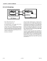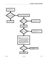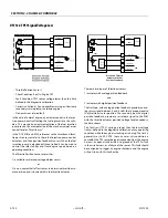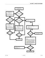
SECTION 3 - CHASSIS & TURNTABLE
3121290
– JLG Lift –
3-111
The desired action is set by OEM calibration engineers.
Fault/Diagnostic Trouble Code Interaction
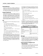
All fault and diagnostic information is managed through the
Faults page. Interaction includes viewing fault messages,
downloading fault data (fault snapshot and flight data
recorder), erasing faults from memory, and defining variables
for fault data logging.
Faults are separated into two categories, Active and Historic.
Active faults are active in real-time and historic faults have
been generated at some instance in time that may or may not
be active in real-time. Once a fault has become active, it is
immediately logged as historic and a snapshot and flight data
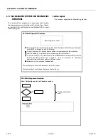
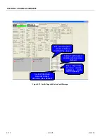
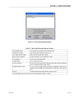
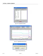
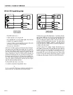
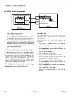
log is saved. Figure 3-72. shows an example of the fault page
when an active fault has been generated. Notice fault is pres-
ent in active and historic lists and the Malfunction Indicator
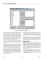
Lamp (MIL) has been illuminated. Figure 3-73. shows an exam-
ple of the fault page with a historic fault stored in memory.
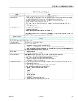
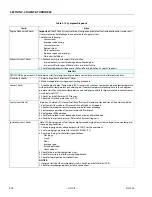
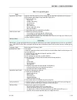
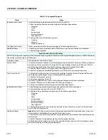
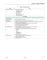
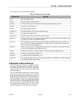
Table 3-16. Diagnostic Corrective Actions
CORRECTIVE ACTION
DESCRIPTION
Enable
Enables the fault for fault detection
Shutdown
Cause an engine shutdown when fault becomes active
Never Forget
Retain fault as historic/previously active until cleared by a technician and does not allow historic fault to be “auto-cleared”
Turn on MIL
Turn on MIL output when fault becomes active
CL Disable
Disable closed-loop while the fault is active
CL Disable Key- Cyc
Disable closed-loop while the fault is active and for the remainder of the key cycle
AL Disable
Disable adaptive learn while the fault is active
AL Disable Key-Cyc
Disable adaptive learn while the fault is active and for the remainder of the key cycle
Power Derate 1
Limit TPS to the Power Derate 1 percent set in the diagnostic calibration while the fault is active. The Power Derate 1 TPS percent should be set higher
than Power Derate 2 as Power Derate 2 adds a higher level of protection.
Power Derate 2
Limit TPS to the Power Derate 2 percent set in the diagnostic calibration while the fault is active. If the calibration is set to “Latched for Key-Cycle”
Power Derate 2 remains active until engine speed and FPP conditions are satisfied. The Power Derate 2 TPS percent should be set lower than Power
Derate 1 as Power Derate 2 adds a higher level of protection.
Low Rev Limit
Limit RPM to the Low Rev Limit speed set in the diagnostic calibration while the fault is active. If the calibration is set to “Latched for Key-Cycle” Low
Rev Limit remains active until engine speed and FPP conditions are satisfied.
Forced Idle
Limit RPM to the Forced Idle speed set in the diagnostic calibration while the fault is active and for the remainder of the key cycle
Soft Warning
Turn on the soft warning output when the fault becomes active
Hard Warning
Turn on the hard warning output when the fault becomes active
Stopped Check
Run fault detection/checking while the engine is in a key-on, engine-off condition. NOTE: It is recommended that this feature only be used for general
sensor faults (high/low voltage) and some output drivers
Summary of Contents for 450A II Series
Page 46: ...SECTION 3 CHASSIS TURNTABLE 3 6 JLG Lift 3121290 Figure 3 4 Drive Hub 4WD Front Only ...
Page 79: ...SECTION 3 CHASSIS TURNTABLE 3121290 JLG Lift 3 39 Figure 3 32 Swing Bearing Drive ...
Page 101: ...SECTION 3 CHASSIS TURNTABLE 3121290 JLG Lift 3 61 Figure 3 42 Auxiliary Pump ...
Page 113: ...SECTION 3 CHASSIS TURNTABLE 3121290 JLG Lift 3 73 Figure 3 53 EMR2 Fault Codes Sheet 1 of 5 ...
Page 114: ...SECTION 3 CHASSIS TURNTABLE 3 74 JLG Lift 3121290 Figure 3 54 EMR2 Fault Codes Sheet 2 of 5 ...
Page 115: ...SECTION 3 CHASSIS TURNTABLE 3121290 JLG Lift 3 75 Figure 3 55 EMR2 Fault Codes Sheet 3 of 5 ...
Page 116: ...SECTION 3 CHASSIS TURNTABLE 3 76 JLG Lift 3121290 Figure 3 56 EMR2 Fault Codes Sheet 4 of 5 ...
Page 117: ...SECTION 3 CHASSIS TURNTABLE 3121290 JLG Lift 3 77 Figure 3 57 EMR2 Fault Codes Sheet 5 of 5 ...
Page 159: ...SECTION 3 CHASSIS TURNTABLE 3121290 JLG Lift 3 119 ...
Page 161: ...SECTION 3 CHASSIS TURNTABLE 3121290 JLG Lift 3 121 ...
Page 163: ...SECTION 3 CHASSIS TURNTABLE 3121290 JLG Lift 3 123 ...
Page 165: ...SECTION 3 CHASSIS TURNTABLE 3121290 JLG Lift 3 125 ...
Page 173: ...SECTION 3 CHASSIS TURNTABLE 3121290 JLG Lift 3 133 Sensor Transducer Type ...
Page 177: ...SECTION 3 CHASSIS TURNTABLE 3121290 JLG Lift 3 137 Sensor Transducer Type ...
Page 179: ...SECTION 3 CHASSIS TURNTABLE 3121290 JLG Lift 3 139 ...
Page 181: ...SECTION 3 CHASSIS TURNTABLE 3121290 JLG Lift 3 141 ...
Page 183: ...SECTION 3 CHASSIS TURNTABLE 3121290 JLG Lift 3 143 ...
Page 185: ...SECTION 3 CHASSIS TURNTABLE 3121290 JLG Lift 3 145 ...
Page 187: ...SECTION 3 CHASSIS TURNTABLE 3121290 JLG Lift 3 147 ...
Page 203: ...SECTION 3 CHASSIS TURNTABLE 3121290 JLG Lift 3 163 ...
Page 207: ...SECTION 3 CHASSIS TURNTABLE 3121290 JLG Lift 3 167 ...
Page 217: ...SECTION 4 BOOM PLATFORM 3121290 JLG Lift 4 5 Figure 4 2 Boom Limit Switches ...
Page 310: ...SECTION 5 HYDRAULICS 5 70 JLG Lift 3121290 NOTES ...
Page 312: ...SECTION 6 JLG CONTROL SYSTEM 6 2 JLG Lift 3121290 Figure 6 2 Controller Block Diagram 0 ...
Page 370: ...SECTION 6 JLG CONTROL SYSTEM 6 60 JLG Lift 3121290 NOTES ...
Page 394: ...SECTION 7 BASIC ELECTRICAL INFORMATION SCHEMATICS 7 24 JLG Lift 3121290 NOTES ...
Page 395: ......

