SECTION 3 - CHASSIS & TURNTABLE
3-120
– JLG Lift –
3121290
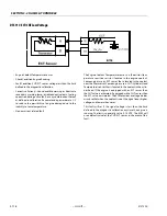
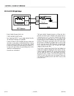
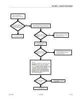
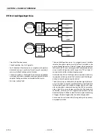
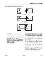
DTC 118- ECT/CHT High Voltage
• Engine Coolant Temperature Sensor
• Check Condition-Engine Running
• Fault Condition-CHT/ECT sensor voltage higher than the
limit defined in the diagnostic calibration
• Corrective Action(s)- Sound audible warning or illuminate
secondary warning lamp, disable adaptive learn fueling
correction during active fault, or any combination thereof
as defined in calibration. Recommend a power derate 1/2
to reduce the possibility of engine damage due to the
inability to sense temperature.
• Non-emissions related fault
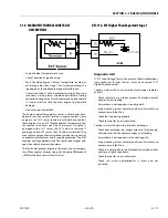
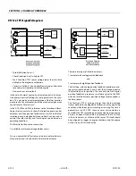
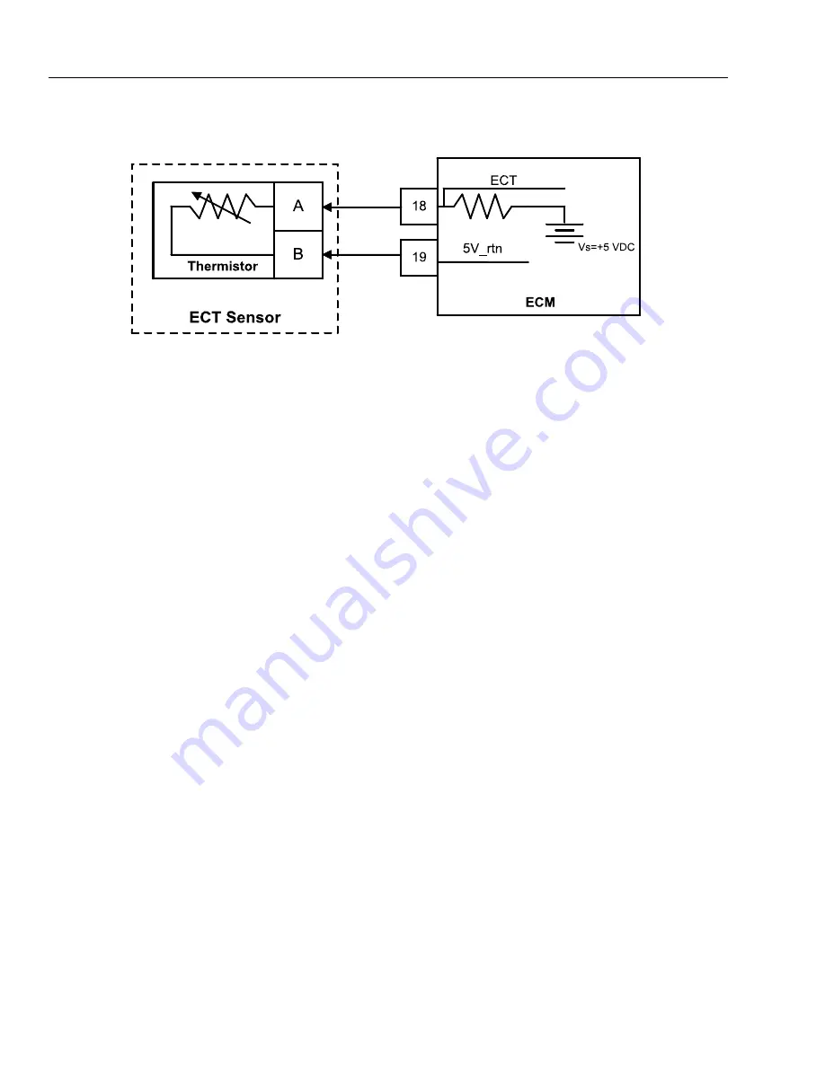
The Engine Coolant Temperature sensor is a thermistor (tem-
perature sensitive resistor) located in the engine coolant.
Some engines use an ECT sensor that is located in the coolant
near the thermostat. Some engines use a CHT (Cylinder Head
Temperature) sensor that is located in the coolant in the cylin-
der head. If the engine is equipped with an ECT sensor then
the CHT value is estimated. If equipped with a CHT sensor then
the ECT value is estimated. The ECM provides a voltage divider
circuit so that when the coolant is cool, the signal reads higher
voltage, and lower when warm.
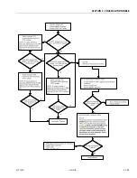
This fault sets if signal voltage is higher than high voltage limit
as defined in diagnostic calibration anytime engine is running.
The limit is generally set to 4.90 VDC. In many cases, this condi-
tion is caused by the CHT/ECT sensor being disconnected from
the engine harness, an open-circuit or short-to-power of the
CHT/ECT circuit in the wire harness, or a failure of the sensor.
The ECM will use a default value for the CHT/ECT sensor in the
event of this fault.
Summary of Contents for 450A II Series
Page 46: ...SECTION 3 CHASSIS TURNTABLE 3 6 JLG Lift 3121290 Figure 3 4 Drive Hub 4WD Front Only ...
Page 79: ...SECTION 3 CHASSIS TURNTABLE 3121290 JLG Lift 3 39 Figure 3 32 Swing Bearing Drive ...
Page 101: ...SECTION 3 CHASSIS TURNTABLE 3121290 JLG Lift 3 61 Figure 3 42 Auxiliary Pump ...
Page 113: ...SECTION 3 CHASSIS TURNTABLE 3121290 JLG Lift 3 73 Figure 3 53 EMR2 Fault Codes Sheet 1 of 5 ...
Page 114: ...SECTION 3 CHASSIS TURNTABLE 3 74 JLG Lift 3121290 Figure 3 54 EMR2 Fault Codes Sheet 2 of 5 ...
Page 115: ...SECTION 3 CHASSIS TURNTABLE 3121290 JLG Lift 3 75 Figure 3 55 EMR2 Fault Codes Sheet 3 of 5 ...
Page 116: ...SECTION 3 CHASSIS TURNTABLE 3 76 JLG Lift 3121290 Figure 3 56 EMR2 Fault Codes Sheet 4 of 5 ...
Page 117: ...SECTION 3 CHASSIS TURNTABLE 3121290 JLG Lift 3 77 Figure 3 57 EMR2 Fault Codes Sheet 5 of 5 ...
Page 159: ...SECTION 3 CHASSIS TURNTABLE 3121290 JLG Lift 3 119 ...
Page 161: ...SECTION 3 CHASSIS TURNTABLE 3121290 JLG Lift 3 121 ...
Page 163: ...SECTION 3 CHASSIS TURNTABLE 3121290 JLG Lift 3 123 ...
Page 165: ...SECTION 3 CHASSIS TURNTABLE 3121290 JLG Lift 3 125 ...
Page 173: ...SECTION 3 CHASSIS TURNTABLE 3121290 JLG Lift 3 133 Sensor Transducer Type ...
Page 177: ...SECTION 3 CHASSIS TURNTABLE 3121290 JLG Lift 3 137 Sensor Transducer Type ...
Page 179: ...SECTION 3 CHASSIS TURNTABLE 3121290 JLG Lift 3 139 ...
Page 181: ...SECTION 3 CHASSIS TURNTABLE 3121290 JLG Lift 3 141 ...
Page 183: ...SECTION 3 CHASSIS TURNTABLE 3121290 JLG Lift 3 143 ...
Page 185: ...SECTION 3 CHASSIS TURNTABLE 3121290 JLG Lift 3 145 ...
Page 187: ...SECTION 3 CHASSIS TURNTABLE 3121290 JLG Lift 3 147 ...
Page 203: ...SECTION 3 CHASSIS TURNTABLE 3121290 JLG Lift 3 163 ...
Page 207: ...SECTION 3 CHASSIS TURNTABLE 3121290 JLG Lift 3 167 ...
Page 217: ...SECTION 4 BOOM PLATFORM 3121290 JLG Lift 4 5 Figure 4 2 Boom Limit Switches ...
Page 310: ...SECTION 5 HYDRAULICS 5 70 JLG Lift 3121290 NOTES ...
Page 312: ...SECTION 6 JLG CONTROL SYSTEM 6 2 JLG Lift 3121290 Figure 6 2 Controller Block Diagram 0 ...
Page 370: ...SECTION 6 JLG CONTROL SYSTEM 6 60 JLG Lift 3121290 NOTES ...
Page 394: ...SECTION 7 BASIC ELECTRICAL INFORMATION SCHEMATICS 7 24 JLG Lift 3121290 NOTES ...
Page 395: ......

