SECTION 4 - BOOM & PLATFORM
3121290
– JLG Lift –
4-1
SECTION 4. BOOM & PLATFORM
4.1
BOOM MAINTENANCE
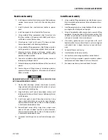
DO NOT USE A LIFTING DEVICE TO LIFT BOOMS UNLESS
HOLDING VALVES HAVE BEEN REMOVED FIRST. FAILURE
TO DO SO WILL RESULT IN SEVERE DAMAGE TO BOOM.
Remove Boom Assembly
1.
Remove platform and platform support as follows:
a.
Disconnect control console electrical cable.
b.
Tag and disconnect rotate cylinder hydraulic lines.
Use a suitable container to retain residual hydraulic
fluid. Cap hydraulic lines and ports.
c.
Use an appropriately rated overhead crane or suit-
able lifting device and nylon support straps to sup-
port the platform/support.
NOTE:
Properly support cylinder when removing retaining pin
from rod end of level cylinder.
d.
Remove bolts and keeper pins from retaining pins.
Remove retaining pins from platform support using
suitable brass drift and hammer.
2.
Remove boom from turntable as follows:
a.
Disconnect wiring harness from ground control har-
ness connector.
CAP HYDRAULIC LINES AND PORTS IMMEDIATELY AFTER DISCONNECTING
LINES TO PREVENT ENTRY OF CONTAMINANTS INTO SYSTEM.
b.
Tag and disconnect boom to control valve hydraulic
lines. Use a suitable container to retain residual
hydraulic fluid. Cap all hydraulic lines and ports.
c.
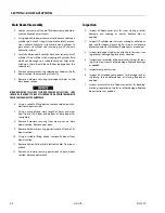
Support boom weight along entire length with
appropriately rated lifting equipment.
d.
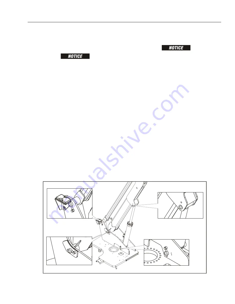
Remove bolts and keeper pins from lift cylinder
pivot pin. Using a suitable brass drift and hammer,
remove pivot pin from lower boom.
NOTE:
To gain access for removal of pivot pins, it may be neces-
sary to remove ground control box, hydraulic and fuel
tanks, and counterweight.
e.
Remove retaining hardware from level link pivot
pin. Using a suitable brass drift and hammer,
remove pin from level link and turntable.
f.
Remove hardware securing lower boom pivot pin.
Using a suitable brass drift and hammer, remove pin
from the turntable.
g.
Using all applicable safety precautions, carefully lift
boom assembly clear of turntable and lower to
ground or suitable supported work surface.
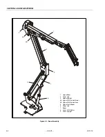
Figure 4-1. Location of Components - Boom Removal
Summary of Contents for 450A II Series
Page 46: ...SECTION 3 CHASSIS TURNTABLE 3 6 JLG Lift 3121290 Figure 3 4 Drive Hub 4WD Front Only ...
Page 79: ...SECTION 3 CHASSIS TURNTABLE 3121290 JLG Lift 3 39 Figure 3 32 Swing Bearing Drive ...
Page 101: ...SECTION 3 CHASSIS TURNTABLE 3121290 JLG Lift 3 61 Figure 3 42 Auxiliary Pump ...
Page 113: ...SECTION 3 CHASSIS TURNTABLE 3121290 JLG Lift 3 73 Figure 3 53 EMR2 Fault Codes Sheet 1 of 5 ...
Page 114: ...SECTION 3 CHASSIS TURNTABLE 3 74 JLG Lift 3121290 Figure 3 54 EMR2 Fault Codes Sheet 2 of 5 ...
Page 115: ...SECTION 3 CHASSIS TURNTABLE 3121290 JLG Lift 3 75 Figure 3 55 EMR2 Fault Codes Sheet 3 of 5 ...
Page 116: ...SECTION 3 CHASSIS TURNTABLE 3 76 JLG Lift 3121290 Figure 3 56 EMR2 Fault Codes Sheet 4 of 5 ...
Page 117: ...SECTION 3 CHASSIS TURNTABLE 3121290 JLG Lift 3 77 Figure 3 57 EMR2 Fault Codes Sheet 5 of 5 ...
Page 159: ...SECTION 3 CHASSIS TURNTABLE 3121290 JLG Lift 3 119 ...
Page 161: ...SECTION 3 CHASSIS TURNTABLE 3121290 JLG Lift 3 121 ...
Page 163: ...SECTION 3 CHASSIS TURNTABLE 3121290 JLG Lift 3 123 ...
Page 165: ...SECTION 3 CHASSIS TURNTABLE 3121290 JLG Lift 3 125 ...
Page 173: ...SECTION 3 CHASSIS TURNTABLE 3121290 JLG Lift 3 133 Sensor Transducer Type ...
Page 177: ...SECTION 3 CHASSIS TURNTABLE 3121290 JLG Lift 3 137 Sensor Transducer Type ...
Page 179: ...SECTION 3 CHASSIS TURNTABLE 3121290 JLG Lift 3 139 ...
Page 181: ...SECTION 3 CHASSIS TURNTABLE 3121290 JLG Lift 3 141 ...
Page 183: ...SECTION 3 CHASSIS TURNTABLE 3121290 JLG Lift 3 143 ...
Page 185: ...SECTION 3 CHASSIS TURNTABLE 3121290 JLG Lift 3 145 ...
Page 187: ...SECTION 3 CHASSIS TURNTABLE 3121290 JLG Lift 3 147 ...
Page 203: ...SECTION 3 CHASSIS TURNTABLE 3121290 JLG Lift 3 163 ...
Page 207: ...SECTION 3 CHASSIS TURNTABLE 3121290 JLG Lift 3 167 ...
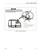
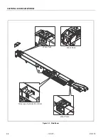
Page 217: ...SECTION 4 BOOM PLATFORM 3121290 JLG Lift 4 5 Figure 4 2 Boom Limit Switches ...
Page 310: ...SECTION 5 HYDRAULICS 5 70 JLG Lift 3121290 NOTES ...
Page 312: ...SECTION 6 JLG CONTROL SYSTEM 6 2 JLG Lift 3121290 Figure 6 2 Controller Block Diagram 0 ...
Page 370: ...SECTION 6 JLG CONTROL SYSTEM 6 60 JLG Lift 3121290 NOTES ...
Page 394: ...SECTION 7 BASIC ELECTRICAL INFORMATION SCHEMATICS 7 24 JLG Lift 3121290 NOTES ...
Page 395: ......

