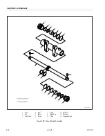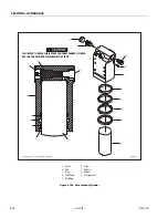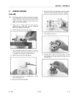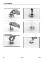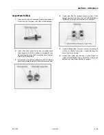
SECTION 5 - HYDRAULICS
5-46
– JLG Lift –
3121290
4.
Using suitable protection, clamp cylinder rod in a vise or
similar holding fixture as close to piston as possible.
5.
Carefully thread piston on cylinder rod hand tight.
Ensure O-ring and back-up rings are not damaged or
dislodged.
NOTE:
Piston and mating end of rod must be free of oil when
installing tapered bushing.
6.
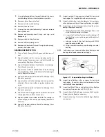
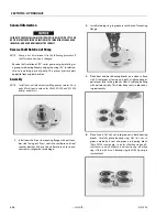
Thread piston on rod until tight. Install tapered bushing.
APPLY JLG THREAD LOCKING COMPOUND P/N 0100011 TO TAPERED BUSHING
BOLTS WHEN REBUILDING MASTER, SLAVE, LIFT, AND TELESCOPE CYLINDERS.
TORQUE TO SPECIFICATIONS.
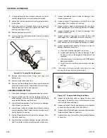
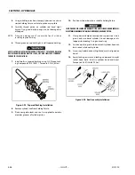
7.
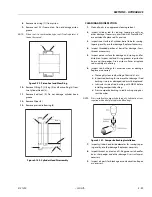
Install bolts in tapered bushing using JLG Thread Lock-
ing Compound P/N 0100011. Torque to 5 ft-lb (6 Nm).
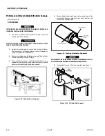
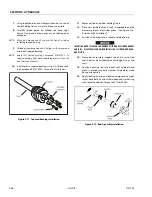
Figure 5-93. Tapered Bushing Installation
8.
Remove cylinder rod from holding fixture.
9.
Place new guide locks and seals in applicable outside
diameter grooves of cylinder piston.
10.
Position cylinder barrel in a suitable holding fixture.
INSERTING ROD OFF-CENTER CAN DAMAGE PISTON AND CYLINDER BARREL SURFACES.
USE EXTREME CARE WHEN INSTALLING CYLINDER ROD, HEAD, AND PISTON.
11.
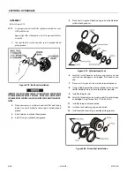
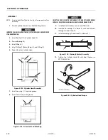
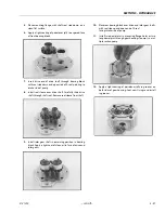
Clamp barrel clamped securely and support rod. Insert
piston end into barrel cylinder. Do not damage or dis-
lodge piston loading O-ring and seal ring.
12.
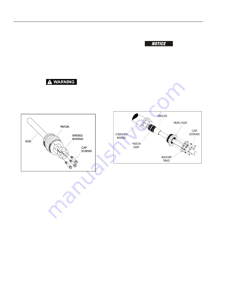
Continue pushing rod into barrel until cylinder head can
be inserted into barrel cylinder.
13.
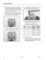
Screw in cylinder head until tight and mark is aligned on
barrel.
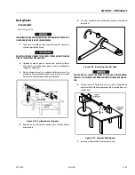
14.
Apply locking primer and locking compound to eight
socket head bolts. Install in cylinder head and barrel.
Torque to 50-55 ft-lb (68-75 Nm).
Figure 5-94. Rod Assembly Installation
Summary of Contents for 450A II Series
Page 46: ...SECTION 3 CHASSIS TURNTABLE 3 6 JLG Lift 3121290 Figure 3 4 Drive Hub 4WD Front Only ...
Page 79: ...SECTION 3 CHASSIS TURNTABLE 3121290 JLG Lift 3 39 Figure 3 32 Swing Bearing Drive ...
Page 101: ...SECTION 3 CHASSIS TURNTABLE 3121290 JLG Lift 3 61 Figure 3 42 Auxiliary Pump ...
Page 113: ...SECTION 3 CHASSIS TURNTABLE 3121290 JLG Lift 3 73 Figure 3 53 EMR2 Fault Codes Sheet 1 of 5 ...
Page 114: ...SECTION 3 CHASSIS TURNTABLE 3 74 JLG Lift 3121290 Figure 3 54 EMR2 Fault Codes Sheet 2 of 5 ...
Page 115: ...SECTION 3 CHASSIS TURNTABLE 3121290 JLG Lift 3 75 Figure 3 55 EMR2 Fault Codes Sheet 3 of 5 ...
Page 116: ...SECTION 3 CHASSIS TURNTABLE 3 76 JLG Lift 3121290 Figure 3 56 EMR2 Fault Codes Sheet 4 of 5 ...
Page 117: ...SECTION 3 CHASSIS TURNTABLE 3121290 JLG Lift 3 77 Figure 3 57 EMR2 Fault Codes Sheet 5 of 5 ...
Page 159: ...SECTION 3 CHASSIS TURNTABLE 3121290 JLG Lift 3 119 ...
Page 161: ...SECTION 3 CHASSIS TURNTABLE 3121290 JLG Lift 3 121 ...
Page 163: ...SECTION 3 CHASSIS TURNTABLE 3121290 JLG Lift 3 123 ...
Page 165: ...SECTION 3 CHASSIS TURNTABLE 3121290 JLG Lift 3 125 ...
Page 173: ...SECTION 3 CHASSIS TURNTABLE 3121290 JLG Lift 3 133 Sensor Transducer Type ...
Page 177: ...SECTION 3 CHASSIS TURNTABLE 3121290 JLG Lift 3 137 Sensor Transducer Type ...
Page 179: ...SECTION 3 CHASSIS TURNTABLE 3121290 JLG Lift 3 139 ...
Page 181: ...SECTION 3 CHASSIS TURNTABLE 3121290 JLG Lift 3 141 ...
Page 183: ...SECTION 3 CHASSIS TURNTABLE 3121290 JLG Lift 3 143 ...
Page 185: ...SECTION 3 CHASSIS TURNTABLE 3121290 JLG Lift 3 145 ...
Page 187: ...SECTION 3 CHASSIS TURNTABLE 3121290 JLG Lift 3 147 ...
Page 203: ...SECTION 3 CHASSIS TURNTABLE 3121290 JLG Lift 3 163 ...
Page 207: ...SECTION 3 CHASSIS TURNTABLE 3121290 JLG Lift 3 167 ...
Page 217: ...SECTION 4 BOOM PLATFORM 3121290 JLG Lift 4 5 Figure 4 2 Boom Limit Switches ...
Page 310: ...SECTION 5 HYDRAULICS 5 70 JLG Lift 3121290 NOTES ...
Page 312: ...SECTION 6 JLG CONTROL SYSTEM 6 2 JLG Lift 3121290 Figure 6 2 Controller Block Diagram 0 ...
Page 370: ...SECTION 6 JLG CONTROL SYSTEM 6 60 JLG Lift 3121290 NOTES ...
Page 394: ...SECTION 7 BASIC ELECTRICAL INFORMATION SCHEMATICS 7 24 JLG Lift 3121290 NOTES ...
Page 395: ......

