SECTION 3 - CHASSIS & TURNTABLE
3-40
– JLG Lift –
3121290
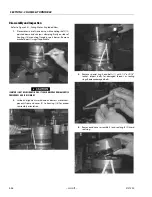
Assembly
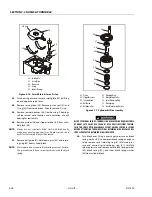
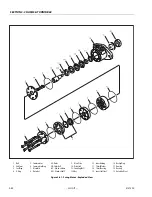
Refer to Figure 3-32., Swing Bearing Drive.
1.
Press bearing (17) in gear cap (12).
2.
Place bearing (30) in housing (4).
3.
Place face seal (18) and O-ring (19) on hub of worm gear
(20).
4.
Place worm gear (20) on press with face seal up. Press
pinion (10) into worm gear. Place grease ring (16) on pin-
ion with cup shape up.
5.
Turn assembly over. Place spacer (21), with hub facing
up, on pinion against gear hub.
6.
Press bearing (22) on pinion and tight to spacer and
gear.
7.
Place pinion gear assembly in housing. Place gear cap
(12) and shims (13) over gear/pinion assembly to
achieve a slight preload on pinion bearings. Remove cap
and shims and set shims aside.
8.
Install new cover plate (9) on cap (12) with six screws
(14) and shims (15) equal or close to total thickness of
shims removed. Apply sealant (Permatex #2 or equiva-
lent) to both sides of each shim and tighten screws, tak-
ing care not to twist screws off. Set assembly aside.
ROLLER BEARINGS MUST BE INSTALLED WITH SMALL ENDS FACING OUT ON
EACH SIDE OF MACHINE OR EXCESSIVE PLAY WILL CAUSE BINDING AND DAM-
AGE TO EQUIPMENT.
9.
Install bearing (30) with small end facing to outside of
machine in motor end of housing (4).
10.
Install worm (29), hex end facing away from motor side,
into housing (4).
IF COMPRESSED AIR OR ELECTRICALLY OPERATED IMPACT WRENCH IS USED
FOR TIGHTENING THE BEARING ATTACHMENT BOLTS, THE TORQUE SETTING
ACCURACY OF THE TOOL SHOULD BE CHECKED PRIOR TO USE.
11.
Install motor adapter (23) and shim (24) to bore end of
housing.
12.
Install bearing (31) with small end facing to outside of
machine on hex end of worm (29).
13.
Install worm cap (26) using shims (27) to achieve 0.000
to 0.001" end play. Install bolts (25) and sealant. Torque
to 80 ft-lb (108.5 Nm).
14.
Install pinion/gear assembly in housing so gear teeth
mesh with worm gear teeth.
15.
Apply silicone sealant to cap assembly contact area on
housing.
16.
Place gear cap assembly over pinion assembly and
install shims set aside in Step 6.
17.
Install eight 12 point screws (11). Torque to 60 ft-lb (81 Nm).
18.
Install two small screws (8).
19.
Install seal (28) in worm cap (26).
20.
Install motor (1) to adapter (23) with two bolts (2), washers
(3), and sealant. Torque to 80 ft-lb (108 Nm).
21.
Install turntable bearing (7) to housing (4) with two bolts (5)
and washers (6).
22.
Fill worm gear with Mobil SHC 460 grease.
23.
Grease pinion gear with Lubriplate No. 930-AAA.
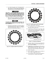
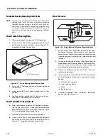
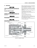
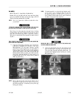
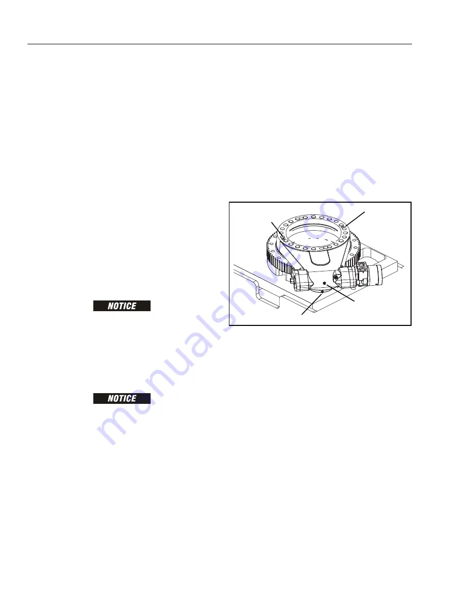
Figure 3-33. Swing Bearing Lubrication Points
Installation
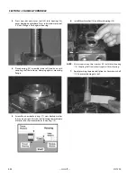
Refer to Figure 3-31., Swing Bearing Installation.
1.
Install bearing to rotation box with two capscrews, with
fill plug of bearing close to gear as bolt pattern allows.
Do not tighten capscrews.
2.
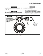
Line up high spot (blue) of bearing with center tooth of
worm gear. Set backlash to 0.008 - 0.010 inch (0.20 - 0.25
mm). Tighten capscrews as shown in Figure 3-34., Swing
Bearing (Dohi) Torque Sequence.
3.
Apply Mobiltac 375 Open Gear Compound or equiva-
lent to bearing and worm gear teeth.
NOTE:
Use Multi-Purpose Grease (MPG) If Mobiltac 375 Open Gear
Compound is not available. However, service interval will
be shorter.
4.
Remove plugs at two locations on top of gear and fill
bearing with Mobil SHC 460 grease. Reinstall plugs.
Pinion Lube Point
Worm Gear
Lube Point
Bearing
Lube Point
Bearing
Lube Point
Summary of Contents for 450A II Series
Page 46: ...SECTION 3 CHASSIS TURNTABLE 3 6 JLG Lift 3121290 Figure 3 4 Drive Hub 4WD Front Only ...
Page 79: ...SECTION 3 CHASSIS TURNTABLE 3121290 JLG Lift 3 39 Figure 3 32 Swing Bearing Drive ...
Page 101: ...SECTION 3 CHASSIS TURNTABLE 3121290 JLG Lift 3 61 Figure 3 42 Auxiliary Pump ...
Page 113: ...SECTION 3 CHASSIS TURNTABLE 3121290 JLG Lift 3 73 Figure 3 53 EMR2 Fault Codes Sheet 1 of 5 ...
Page 114: ...SECTION 3 CHASSIS TURNTABLE 3 74 JLG Lift 3121290 Figure 3 54 EMR2 Fault Codes Sheet 2 of 5 ...
Page 115: ...SECTION 3 CHASSIS TURNTABLE 3121290 JLG Lift 3 75 Figure 3 55 EMR2 Fault Codes Sheet 3 of 5 ...
Page 116: ...SECTION 3 CHASSIS TURNTABLE 3 76 JLG Lift 3121290 Figure 3 56 EMR2 Fault Codes Sheet 4 of 5 ...
Page 117: ...SECTION 3 CHASSIS TURNTABLE 3121290 JLG Lift 3 77 Figure 3 57 EMR2 Fault Codes Sheet 5 of 5 ...
Page 159: ...SECTION 3 CHASSIS TURNTABLE 3121290 JLG Lift 3 119 ...
Page 161: ...SECTION 3 CHASSIS TURNTABLE 3121290 JLG Lift 3 121 ...
Page 163: ...SECTION 3 CHASSIS TURNTABLE 3121290 JLG Lift 3 123 ...
Page 165: ...SECTION 3 CHASSIS TURNTABLE 3121290 JLG Lift 3 125 ...
Page 173: ...SECTION 3 CHASSIS TURNTABLE 3121290 JLG Lift 3 133 Sensor Transducer Type ...
Page 177: ...SECTION 3 CHASSIS TURNTABLE 3121290 JLG Lift 3 137 Sensor Transducer Type ...
Page 179: ...SECTION 3 CHASSIS TURNTABLE 3121290 JLG Lift 3 139 ...
Page 181: ...SECTION 3 CHASSIS TURNTABLE 3121290 JLG Lift 3 141 ...
Page 183: ...SECTION 3 CHASSIS TURNTABLE 3121290 JLG Lift 3 143 ...
Page 185: ...SECTION 3 CHASSIS TURNTABLE 3121290 JLG Lift 3 145 ...
Page 187: ...SECTION 3 CHASSIS TURNTABLE 3121290 JLG Lift 3 147 ...
Page 203: ...SECTION 3 CHASSIS TURNTABLE 3121290 JLG Lift 3 163 ...
Page 207: ...SECTION 3 CHASSIS TURNTABLE 3121290 JLG Lift 3 167 ...
Page 217: ...SECTION 4 BOOM PLATFORM 3121290 JLG Lift 4 5 Figure 4 2 Boom Limit Switches ...
Page 310: ...SECTION 5 HYDRAULICS 5 70 JLG Lift 3121290 NOTES ...
Page 312: ...SECTION 6 JLG CONTROL SYSTEM 6 2 JLG Lift 3121290 Figure 6 2 Controller Block Diagram 0 ...
Page 370: ...SECTION 6 JLG CONTROL SYSTEM 6 60 JLG Lift 3121290 NOTES ...
Page 394: ...SECTION 7 BASIC ELECTRICAL INFORMATION SCHEMATICS 7 24 JLG Lift 3121290 NOTES ...
Page 395: ......

