SECTION 3 - CHASSIS & TURNTABLE
3121290
– JLG Lift –
3-89
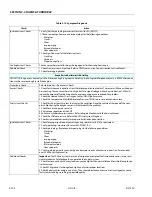
Check/Drain Oil Build-Up In 2-Stage Vaporizer
NOTE:
Refer to Figure 3-59. GM 3.0 Dual Fuel System Components.
During normal operation for LPG engines oil or “heavy ends”
may build inside the Vaporizer secondary chamber. These oil
and heavy ends may be a result of poor fuel quality, fuel con-
tamination, or regional variation of the fuel make up. A signifi-
cant build up of oil can affect performance of the secondary
diaphragm response.
FAILURE TO FOLLOW THIS RECOMMENDATION MAY BE USED TO DENY A WAR-
RANTY CLAIM.
Drain oil periodically to maintain emission warranty. More fre-
quent draining of the Vaporizer Regulator is recommended
where substandard fuel may be a problem. Drain Vaporizer
Regulator at every engine oil change if contaminated or sub-
standard fuel is suspected or known to be have been used
with the emission compliant fuel system.
NOTE:
Draining regulator when engine is warm will help oils to
flow freely from regulator.
1.
Move equipment well ventilated area and ensure no
external ignition sources are present.
2.
Start engine.
3.
With engine running, close manual valve.
4.
When engine runs out of fuel and stops, turn key OFF.
5.
Disconnect negative battery cable.
A SMALL AMOUNT OF FUEL MAY STILL BE PRESENT IN THE FUEL LINE. USE
GLOVES TO PREVENT BURNS AND WEAR PROPER EYE PROTECTION.
NOTE:
If fuel continues to flow from connections when loosened,
check manual valve is fully closed.
6.
Loosen hose clamps at inlet and outlet hoses. R
emove
hose
s.
7.
Remove regulator mounting bolts.
8.
Place a small receptacle in the engine compartment.
9.
Rotate regulator to 90° so outlet fitting is pointing down
into receptacle. Drain regulator.
10.
Inspect secondary chamber for any large dried particles
and remove.
11.
Remove receptacle and reinstall regulator retaining
bolts. Torque to specifications.
12.
Reinstall fuel hoses. Reconnect any other hoses
removed during this procedure.
13.
Slowly open manual service valve.
FUEL CYLINDER MANUAL VALVE CONTAINS AN “EXCESS FLOW CHECK VALVE”.
OPEN MANUAL VALVE SLOWLY TO PREVENT ACTIVATING THE “EXCESS FLOW
CHECK VALVE.”
14.
Check for leaks at the inlet and outlet fittings using a
soapy solution or an electronic leak detector.
15.
Check coolant line connections for leaks.
16.
15. Start engine. Recheck regulator for leaks.
17.
16. Dispose of any drained material in safe and proper
manner according to applicable regulations.
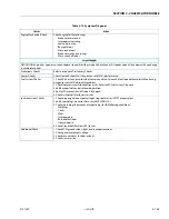
Air Fuel Mixer/Throttle Control Device Maintenance
And Inspection
NOTE:
Refer to Figure 3-59. GM 3.0 Dual Fuel System Components.
AIR FUEL MIXER COMPONENTS HAVE BEEN SPECIFICALLY DESIGNED AND CAL-
IBRATED TO MEET FUEL SYSTEM REQUIREMENTS OF THE EMISSION CERTIFIED
ENGINE. THE MIXER SHOULD NOT BE DISASSEMBLED OR REBUILT. IF MIXER
FAILS TO OPERATE OR DEVELOPS A LEAK, IT SHOULD BE REPLACED WITH OEM
RECOMMENDED REPLACEMENT PARTS.
1.
Check for leaks at the inlet fitting.
2.
Inspect fuel inlet hose for cracking, splitting, or chaff
ing.
R
eplace if any of these condition exist.
3.
Ensure mixer is securely mounted and not leaking vac-
uum at the mounting gasket or surface.
4.
Inspect air inlet hose connection and clamp. Inspect
inlet hose for cracking, splitting, or chafing. Replace if
any of these conditions exist.
5.
Inspect air cleaner element.
6.
Check fuel lines for cracking, splitting, or chafing.
Replace if any of these conditions exist.
7.
Check for leaks at the throttle body and intake manifold.
Summary of Contents for 450A II Series
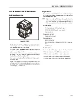
Page 46: ...SECTION 3 CHASSIS TURNTABLE 3 6 JLG Lift 3121290 Figure 3 4 Drive Hub 4WD Front Only ...
Page 79: ...SECTION 3 CHASSIS TURNTABLE 3121290 JLG Lift 3 39 Figure 3 32 Swing Bearing Drive ...
Page 101: ...SECTION 3 CHASSIS TURNTABLE 3121290 JLG Lift 3 61 Figure 3 42 Auxiliary Pump ...
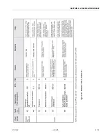
Page 113: ...SECTION 3 CHASSIS TURNTABLE 3121290 JLG Lift 3 73 Figure 3 53 EMR2 Fault Codes Sheet 1 of 5 ...
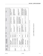
Page 114: ...SECTION 3 CHASSIS TURNTABLE 3 74 JLG Lift 3121290 Figure 3 54 EMR2 Fault Codes Sheet 2 of 5 ...
Page 115: ...SECTION 3 CHASSIS TURNTABLE 3121290 JLG Lift 3 75 Figure 3 55 EMR2 Fault Codes Sheet 3 of 5 ...
Page 116: ...SECTION 3 CHASSIS TURNTABLE 3 76 JLG Lift 3121290 Figure 3 56 EMR2 Fault Codes Sheet 4 of 5 ...
Page 117: ...SECTION 3 CHASSIS TURNTABLE 3121290 JLG Lift 3 77 Figure 3 57 EMR2 Fault Codes Sheet 5 of 5 ...
Page 159: ...SECTION 3 CHASSIS TURNTABLE 3121290 JLG Lift 3 119 ...
Page 161: ...SECTION 3 CHASSIS TURNTABLE 3121290 JLG Lift 3 121 ...
Page 163: ...SECTION 3 CHASSIS TURNTABLE 3121290 JLG Lift 3 123 ...
Page 165: ...SECTION 3 CHASSIS TURNTABLE 3121290 JLG Lift 3 125 ...
Page 173: ...SECTION 3 CHASSIS TURNTABLE 3121290 JLG Lift 3 133 Sensor Transducer Type ...
Page 177: ...SECTION 3 CHASSIS TURNTABLE 3121290 JLG Lift 3 137 Sensor Transducer Type ...
Page 179: ...SECTION 3 CHASSIS TURNTABLE 3121290 JLG Lift 3 139 ...
Page 181: ...SECTION 3 CHASSIS TURNTABLE 3121290 JLG Lift 3 141 ...
Page 183: ...SECTION 3 CHASSIS TURNTABLE 3121290 JLG Lift 3 143 ...
Page 185: ...SECTION 3 CHASSIS TURNTABLE 3121290 JLG Lift 3 145 ...
Page 187: ...SECTION 3 CHASSIS TURNTABLE 3121290 JLG Lift 3 147 ...
Page 203: ...SECTION 3 CHASSIS TURNTABLE 3121290 JLG Lift 3 163 ...
Page 207: ...SECTION 3 CHASSIS TURNTABLE 3121290 JLG Lift 3 167 ...
Page 217: ...SECTION 4 BOOM PLATFORM 3121290 JLG Lift 4 5 Figure 4 2 Boom Limit Switches ...
Page 310: ...SECTION 5 HYDRAULICS 5 70 JLG Lift 3121290 NOTES ...
Page 312: ...SECTION 6 JLG CONTROL SYSTEM 6 2 JLG Lift 3121290 Figure 6 2 Controller Block Diagram 0 ...
Page 370: ...SECTION 6 JLG CONTROL SYSTEM 6 60 JLG Lift 3121290 NOTES ...
Page 394: ...SECTION 7 BASIC ELECTRICAL INFORMATION SCHEMATICS 7 24 JLG Lift 3121290 NOTES ...
Page 395: ......

