SECTION 5 - HYDRAULICS
3121290
– JLG Lift –
5-49
8.
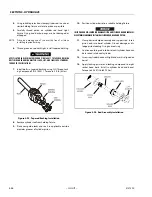
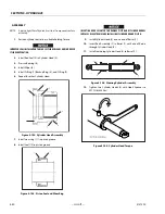
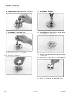
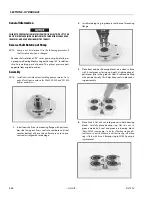
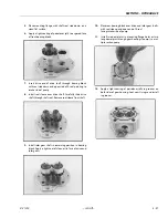
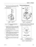
Remove wear ring (11) from piston.
9.
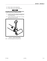
Remove seal (10) from piston. Do not damage piston
groove.
NOTE:
Piston seal is a combination-type seal. If seal separates it
cannot be reused.
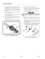
Figure 5-99. Piston Seal and Wear Ring
10.
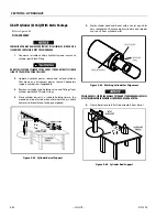
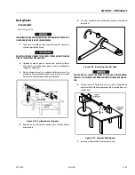
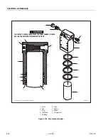
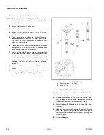
Remove O-Ring (7), O-Ring (9), and Backup Ring (8) from
two Cylinder Heads (3).
11.
Remove Rod Seal (5). Do not damage cylinder head
groove.
12.
Remove Wiper (4).
13.
Remove pressed-in Bearing (6).
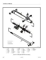
Figure 5-100. Cylinder Head Disassembly
CLEANING AND INSPECTION
1.
Clean all parts in an approved cleaning solvent.
2.
Inspect cylinder rod for scoring, tapering, ovality, or
other damage. If necessary, dress rod with Scotch Brite™
or equivalent. Replace rod if necessary.
3.
Inspect inner surface of cylinder barrel tube for scoring,
tapering, ovality, or other damage. Replace if necessary.
4.
Inspect threaded portion of barrel for damage. Dress
threads as necessary.
5.
Inspect piston surface for damage and scoring and for
distortion. Inspect seal and O-ring grooves in piston for
burrs and sharp edges. Dress piston surfaces or replace
rod assembly as necessary.
6.
Inspect rod bushings for excessive wear or damage.
Replace as necessary.
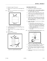
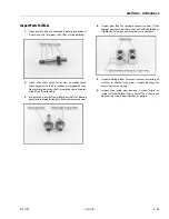
a. Thoroughly clean rod bushing of burrs, dirt, etc.
b. Inspect rod bushing for wear or other damage. If rod
bushing is worn or damaged, rod must be replaced.
c. Lubricate inside of rod bushing with WD40 before
installing composite bushing.
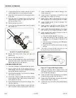
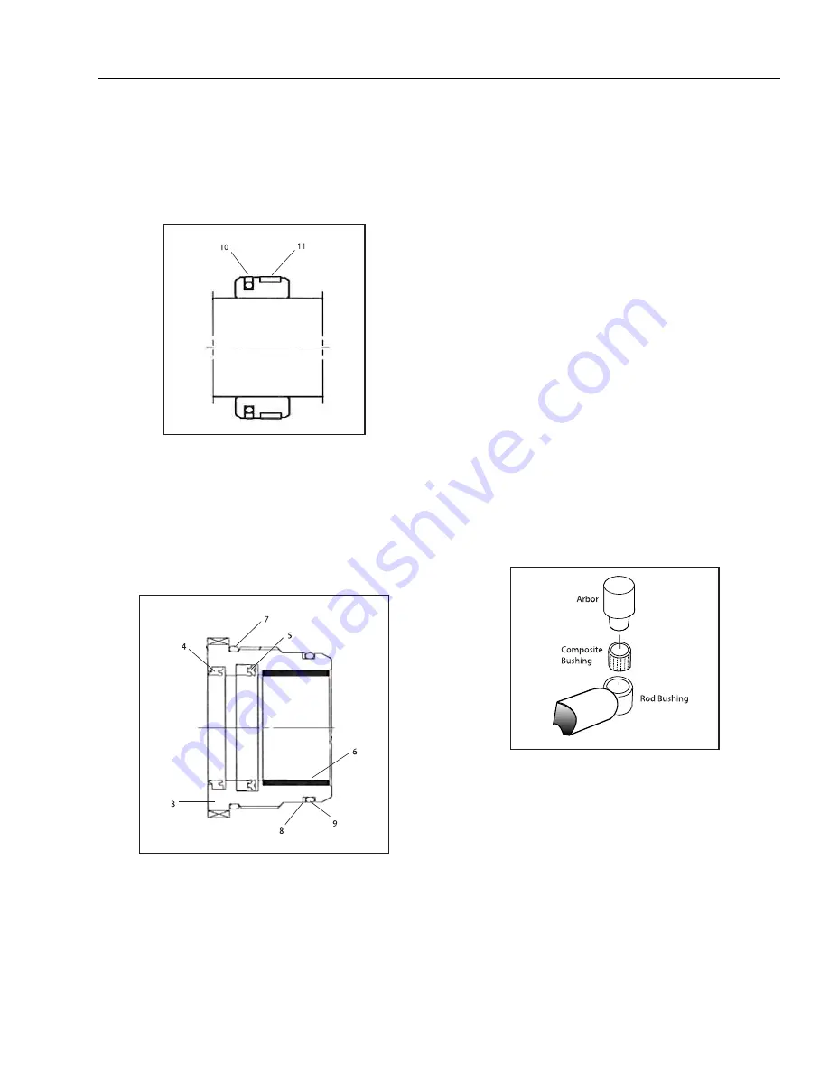
d. Press composite bushing in rod bushing using cor-
rect size arbor.
NOTE:
Pin is installed in composite bushing dry. Lubrication is not
required with nickel plated pins and bearings.
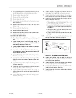
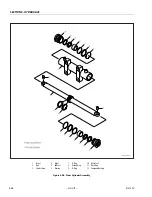
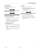
Figure 5-101. Composite Bushing Installation
7.
Inspect cylinder head inside diameter for scoring, taper-
ing, ovality, or other damage. Replace as necessary.
8.
Inspect threads, and seal and O-Ring grooves in head for
burrs, sharp edges, and other damage. Dress surfaces as
necessary.
9.
Inspect oil ports for blockage or contamination. Repair
as necessary.
Summary of Contents for 450A II Series
Page 46: ...SECTION 3 CHASSIS TURNTABLE 3 6 JLG Lift 3121290 Figure 3 4 Drive Hub 4WD Front Only ...
Page 79: ...SECTION 3 CHASSIS TURNTABLE 3121290 JLG Lift 3 39 Figure 3 32 Swing Bearing Drive ...
Page 101: ...SECTION 3 CHASSIS TURNTABLE 3121290 JLG Lift 3 61 Figure 3 42 Auxiliary Pump ...
Page 113: ...SECTION 3 CHASSIS TURNTABLE 3121290 JLG Lift 3 73 Figure 3 53 EMR2 Fault Codes Sheet 1 of 5 ...
Page 114: ...SECTION 3 CHASSIS TURNTABLE 3 74 JLG Lift 3121290 Figure 3 54 EMR2 Fault Codes Sheet 2 of 5 ...
Page 115: ...SECTION 3 CHASSIS TURNTABLE 3121290 JLG Lift 3 75 Figure 3 55 EMR2 Fault Codes Sheet 3 of 5 ...
Page 116: ...SECTION 3 CHASSIS TURNTABLE 3 76 JLG Lift 3121290 Figure 3 56 EMR2 Fault Codes Sheet 4 of 5 ...
Page 117: ...SECTION 3 CHASSIS TURNTABLE 3121290 JLG Lift 3 77 Figure 3 57 EMR2 Fault Codes Sheet 5 of 5 ...
Page 159: ...SECTION 3 CHASSIS TURNTABLE 3121290 JLG Lift 3 119 ...
Page 161: ...SECTION 3 CHASSIS TURNTABLE 3121290 JLG Lift 3 121 ...
Page 163: ...SECTION 3 CHASSIS TURNTABLE 3121290 JLG Lift 3 123 ...
Page 165: ...SECTION 3 CHASSIS TURNTABLE 3121290 JLG Lift 3 125 ...
Page 173: ...SECTION 3 CHASSIS TURNTABLE 3121290 JLG Lift 3 133 Sensor Transducer Type ...
Page 177: ...SECTION 3 CHASSIS TURNTABLE 3121290 JLG Lift 3 137 Sensor Transducer Type ...
Page 179: ...SECTION 3 CHASSIS TURNTABLE 3121290 JLG Lift 3 139 ...
Page 181: ...SECTION 3 CHASSIS TURNTABLE 3121290 JLG Lift 3 141 ...
Page 183: ...SECTION 3 CHASSIS TURNTABLE 3121290 JLG Lift 3 143 ...
Page 185: ...SECTION 3 CHASSIS TURNTABLE 3121290 JLG Lift 3 145 ...
Page 187: ...SECTION 3 CHASSIS TURNTABLE 3121290 JLG Lift 3 147 ...
Page 203: ...SECTION 3 CHASSIS TURNTABLE 3121290 JLG Lift 3 163 ...
Page 207: ...SECTION 3 CHASSIS TURNTABLE 3121290 JLG Lift 3 167 ...
Page 217: ...SECTION 4 BOOM PLATFORM 3121290 JLG Lift 4 5 Figure 4 2 Boom Limit Switches ...
Page 310: ...SECTION 5 HYDRAULICS 5 70 JLG Lift 3121290 NOTES ...
Page 312: ...SECTION 6 JLG CONTROL SYSTEM 6 2 JLG Lift 3121290 Figure 6 2 Controller Block Diagram 0 ...
Page 370: ...SECTION 6 JLG CONTROL SYSTEM 6 60 JLG Lift 3121290 NOTES ...
Page 394: ...SECTION 7 BASIC ELECTRICAL INFORMATION SCHEMATICS 7 24 JLG Lift 3121290 NOTES ...
Page 395: ......


