SECTION 5 - HYDRAULICS
5-56
– JLG Lift –
3121290
General Information
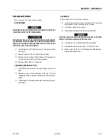
FAILURE TO PROPERLY ASSEMBLE THIS PUMP WILL RESULT WITH LITTLE OR
NO FLOW AT RATED PRESSURE. RELATIONSHIP OF MOUNTING FLANGE, BEAR-
ING BLOCKS, AND GEAR HOUSING MUST BE CORRECT.
Reverse Shaft Rotation of Pump
NOTE:
Pump is not bi-rotational. Use the following procedure if
shaft rotation direction is changed.
Reverse shaft rotation of ”W” series gear pump by rotating, as
a group, two bearing blocks and gear housing 180° in relation-
ship to remaining parts of pump. This places pressure port
opposite from original position.
Assembly
NOTE:
Install new seals when reassembling pump or motor. Go to
page 8 for kit part numbers for W-600, W-900, and W-1500
pumps and motors.
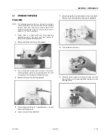
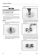
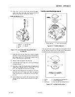
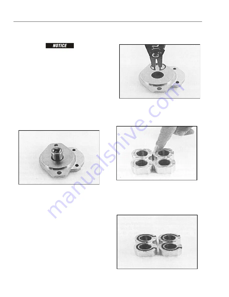
1.
Install new shaft seal in mounting flange with part num-
ber side facing out. Press seal into seal bore until seal
reaches bottom of bore. Use uniform pressure to pre-
vent seal misalignment or damage.
2.
Install retaining ring in groove in seal bore of mounting
flange.
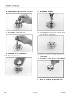
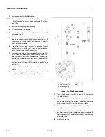
3.
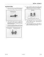
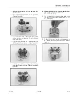
Place front and back bearing blocks on a clean surface
with E-seal grooves facing up. Apply a light coating of
petroleum jelly in the grooves. Coat E-seal and backup
with petroleum jelly. This helps keep seals in place dur-
ing reassembly
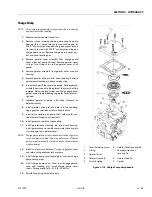
4.
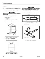
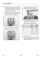
Place E-seals,
flat side out,
into grooves in both bearing
blocks. C
arefully
place backup ring,
flat side out,
in
groove made by E-seal and groove in bearing block.
(Note: W900 series pump - In center of backup ring and E-
seal there is a notch. Make sure notches line up so backup
ring is flush with E-seal).
Backup ring in W1500 pump is
symmetrical.
Summary of Contents for 450A II Series
Page 46: ...SECTION 3 CHASSIS TURNTABLE 3 6 JLG Lift 3121290 Figure 3 4 Drive Hub 4WD Front Only ...
Page 79: ...SECTION 3 CHASSIS TURNTABLE 3121290 JLG Lift 3 39 Figure 3 32 Swing Bearing Drive ...
Page 101: ...SECTION 3 CHASSIS TURNTABLE 3121290 JLG Lift 3 61 Figure 3 42 Auxiliary Pump ...
Page 113: ...SECTION 3 CHASSIS TURNTABLE 3121290 JLG Lift 3 73 Figure 3 53 EMR2 Fault Codes Sheet 1 of 5 ...
Page 114: ...SECTION 3 CHASSIS TURNTABLE 3 74 JLG Lift 3121290 Figure 3 54 EMR2 Fault Codes Sheet 2 of 5 ...
Page 115: ...SECTION 3 CHASSIS TURNTABLE 3121290 JLG Lift 3 75 Figure 3 55 EMR2 Fault Codes Sheet 3 of 5 ...
Page 116: ...SECTION 3 CHASSIS TURNTABLE 3 76 JLG Lift 3121290 Figure 3 56 EMR2 Fault Codes Sheet 4 of 5 ...
Page 117: ...SECTION 3 CHASSIS TURNTABLE 3121290 JLG Lift 3 77 Figure 3 57 EMR2 Fault Codes Sheet 5 of 5 ...
Page 159: ...SECTION 3 CHASSIS TURNTABLE 3121290 JLG Lift 3 119 ...
Page 161: ...SECTION 3 CHASSIS TURNTABLE 3121290 JLG Lift 3 121 ...
Page 163: ...SECTION 3 CHASSIS TURNTABLE 3121290 JLG Lift 3 123 ...
Page 165: ...SECTION 3 CHASSIS TURNTABLE 3121290 JLG Lift 3 125 ...
Page 173: ...SECTION 3 CHASSIS TURNTABLE 3121290 JLG Lift 3 133 Sensor Transducer Type ...
Page 177: ...SECTION 3 CHASSIS TURNTABLE 3121290 JLG Lift 3 137 Sensor Transducer Type ...
Page 179: ...SECTION 3 CHASSIS TURNTABLE 3121290 JLG Lift 3 139 ...
Page 181: ...SECTION 3 CHASSIS TURNTABLE 3121290 JLG Lift 3 141 ...
Page 183: ...SECTION 3 CHASSIS TURNTABLE 3121290 JLG Lift 3 143 ...
Page 185: ...SECTION 3 CHASSIS TURNTABLE 3121290 JLG Lift 3 145 ...
Page 187: ...SECTION 3 CHASSIS TURNTABLE 3121290 JLG Lift 3 147 ...
Page 203: ...SECTION 3 CHASSIS TURNTABLE 3121290 JLG Lift 3 163 ...
Page 207: ...SECTION 3 CHASSIS TURNTABLE 3121290 JLG Lift 3 167 ...
Page 217: ...SECTION 4 BOOM PLATFORM 3121290 JLG Lift 4 5 Figure 4 2 Boom Limit Switches ...
Page 310: ...SECTION 5 HYDRAULICS 5 70 JLG Lift 3121290 NOTES ...
Page 312: ...SECTION 6 JLG CONTROL SYSTEM 6 2 JLG Lift 3121290 Figure 6 2 Controller Block Diagram 0 ...
Page 370: ...SECTION 6 JLG CONTROL SYSTEM 6 60 JLG Lift 3121290 NOTES ...
Page 394: ...SECTION 7 BASIC ELECTRICAL INFORMATION SCHEMATICS 7 24 JLG Lift 3121290 NOTES ...
Page 395: ......

