background image

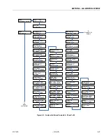
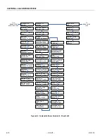
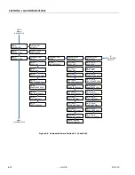
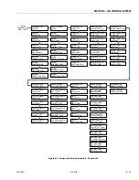
SECTION 5 - HYDRAULICS

5-68

– JLG Lift –

3121290

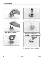
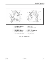
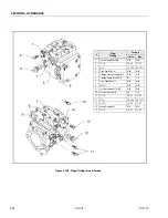
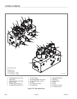
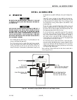
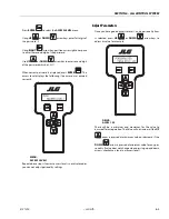
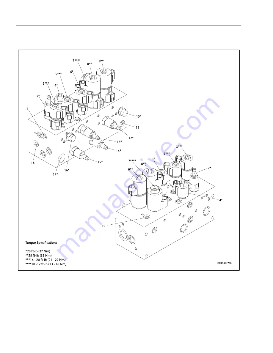
Figure 5-115.  Main Control Valve

1.

M2 - Proportional Main Pressure Test Port

2.

Swing Relief Valve

3.

Swing Solenoid: Bottom - Left, Top - Right

4.

Main Dump Solenoid

5.

Lift Solenoid: Bottom - Down, Top - Up

6.

Steer Solenoid: Bottom - Right, Top - Left

7.

Flow Control Solenoid

8.

Lower Lift Solenoid: Bottom - Down, Top - Up

9.

Telescope Solenoid: Bottom - In, Top - Out

10. Flow Control
11. M1 - Telescope Pressure Test Port
12. Telescope Relief Valve

13. Proportional Main Relief Valve
14. Steer Relief Valve
15. Lift Down Relief Valve
16. Check Valve
17. Check valve
18. M4 - Swing Pressure Test Port
19. M3 - Steer Pressure Test Port

Summary of Contents for 450A II Series

Page 1: ...Service and Maintenance Manual Model 450A Series II 450AJ Series II S N 0300160835 to Present P N 3121290 October 4 2013 ...

Page 2: ...NOTE This manual also applies to machines with the following Serial Numbers 0300159794 0300159795 0300160088 and 0300160456 ...

Page 3: ... OPERATOR B HYDRAULIC SYSTEM SAFETY It should be noted that the machines hydraulic systems oper ate at extremely high potentially dangerous pressures Every effort should be made to relieve any system pressure prior to disconnecting or removing any portion of the system C MAINTENANCE FAILURE TO COMPLY WITH SAFETY PRECAUTIONS LISTED IN THIS SECTION COULD RESULT IN MACHINE DAMAGE PERSONNEL INJURY OR ...

Page 4: ...INTRODUCTION A 2 JLG Lift 3121290 REVISON LOG Original Issue January 10 2013 Revision 1 October 4 2013 ...

Page 5: ...e Delivery Inspection and Frequent Inspection 2 1 Annual Machine Inspection 2 1 Preventative Maintenance 2 1 2 2 Service and Guidelines 2 2 General 2 2 Safety and Workmanship 2 2 Cleanliness 2 2 Components Removal and Installation 2 2 Component Disassembly and Reassembly 2 3 Pressure Fit Parts 2 3 Bearings 2 3 Gaskets 2 3 Battery 2 3 Bolt Usage and Torque Application 2 3 Hydraulic Lines and Electr...

Page 6: ...iption 3 20 Shaft Seal Replacement 3 21 Loop Flushing Valve 3 21 Troubleshooting 3 22 Disassembly 3 23 Inspection 3 27 Assembly 3 29 Initial Start Up Procedures 3 33 3 5 Adjustment Procedure For Lockout Valve 3 35 3 6 Oscillating Axle Bleeding Procedure and Lockout Test 3 35 Lockout Cylinder Bleeding Ram Cylinders 3 35 Oscillating Axle Lockout Test 3 36 3 7 Swing Bearing 3 36 Description 3 36 Remo...

Page 7: ...5 Heated Exhaust Gas Oxygen Sensor 3 86 Gasoline Multi Point Fuel Injection System MPFI 3 86 Gasoline Fuel Pump 3 86 Gasoline Pressure And Temperature Sensor Manifold 3 86 Fuel Filter 3 87 Fuel Injector Rail 3 87 Fuel Injector 3 87 3 15 GM Engine Fuel System Repair 3 87 Propane Fuel System Pressure Relief 3 87 Propane Fuel System Leak Test 3 87 Propane Fuel Filter Replacement 3 88 Direct Electroni...

Page 8: ...01 Microprocessor Failure FLASH 3 142 DTC 604 Microprocessor Failure RAM 3 144 DTC 606 Microprocessor Failure COP 3 146 DTC 642 5 Volt External Low Voltage 3 148 DTC 643 5 Volt External High Voltage 3 149 DTC 1612 Microprocessor Failure RTI 1 3 150 DTC 1613 Microprocessor Failure RTI 2 3 151 DTC 1614 Microprocessor Failure RTI 3 3 153 DTC 1615 Microprocessor Failure A D 3 155 DTC 1616 Microprocess...

Page 9: ...ackage 5 37 Jib Lift Cylinder AJ Only With Arctic Package 5 42 Steer Cylinder 5 47 Axle Lockout Cylinder 5 51 5 3 Hydraulic Pump Gear 5 53 Disassembly 5 53 Inspect Parts For Wear 5 55 General Information 5 56 Reverse Shaft Rotation of Pump 5 56 Assembly 5 56 Placing Pump Back Into Service 5 59 5 4 Variable Pump 5 59 Ports and Pressure Gauges 5 59 NFPE Control 5 59 Remove and Install FNR and NFPE M...

Page 10: ...nding 7 1 Backprobing 7 1 Min Max 7 1 Polarity 7 1 Scale 7 1 Voltage Measurement 7 1 Resistance Measurement 7 2 Continuity Measurement 7 2 Current Measurement 7 3 7 3 Applying Silicone Dielectric Compound to Electrical Connections 7 3 Dielectric Grease Application 7 4 Deutsch HD DT DTM DRC Series 7 4 AMP Seal 7 4 AMP Mate N Lok 7 5 DIN Connectors 7 5 Exclusions 7 5 7 4 AMP Connector 7 6 Contact As...

Page 11: ... 3 25 3 15 Shaft Front Bearing 3 25 3 16 Swash Plate Servo Piston 3 26 3 17 Cylinder Kit Disassembly 3 26 3 18 Servo Piston 3 29 3 19 Cylinder Kit Assembly 3 29 3 20 Swash Plate and Journal Bearing 3 30 3 21 Shaft and Front Bearing 3 30 3 22 Cylinder Kit Installation 3 31 3 23 Servo Spring and Minimum Angle Stop 3 31 3 24 Valve Plate and Rear Bearing 3 31 3 25 End Cap 3 32 3 26 Shaft Seal 3 32 3 2...

Page 12: ...et 1 of 2 3 106 3 71 GM 3 0L Engine Sheet 2 of 2 3 107 3 72 Faults Page with Active Fault Message 3 112 3 73 Faults Page with Historic Fault Message 3 113 3 74 Custom Fault Variable Interface 3 114 3 75 Historic Fault Information Interface 3 115 3 76 Snapshot Data Interface 3 116 3 77 Flight Data Recorder Interface 3 116 3 78 Clear Faults Prompt 3 116 3 79 Exhaust Venturi Adjustment 3 171 3 80 Cou...

Page 13: ...ylinder Rod Support 5 23 5 45 Telescope Cylinder 450A AJ 5 24 5 46 Composite Bushing Installation 5 25 5 47 Rod Seal Installation 5 26 5 48 Cylinder Head Seal Installation 5 26 5 49 Piston Seal Installation 5 26 5 50 Cylinder Barrel Support 5 27 5 51 Cylinder Head Removal 5 27 5 52 Cylinder Rod Support 5 27 5 53 Platform Level Slave Cylinder Assembly 450A 5 28 5 54 Platform Level Slave Cylinder As...

Page 14: ... Cylinder Head Assembly 5 50 5 103 Piston Seal and Wear Ring 5 50 5 104 Steering Cylinder Assembly 5 50 5 105 Cylinder Head Torque 5 50 5 106 Axle Lockout Cylinder 5 52 5 107 Shim Adjustable Charge Relief Valve Components 5 60 5 108 Gauge Port Locations 5 61 5 109 Plugs Fittings Size Torque 5 62 5 110 Screw Adjustable Charge Relief Valve Components 5 63 5 111 Shaft Seal Removal 5 63 5 112 Installa...

Page 15: ...7 8 7 22 HD HDP Contact Installation 7 9 7 23 HD HDP Locking Contacts Into Position 7 9 7 24 HD HDP Contact Removal 7 9 7 25 HD HDP Unlocking Contacts 7 9 7 26 Electrical Components 1 of 2 7 10 7 27 Electrical Components 2 of 2 7 11 7 28 Chassis Platform Electrical Schematic Sheet 1 of 2 7 12 7 29 Chassis Platform Electrical Schematic Sheet 2 of 2 7 13 7 30 Deutz Engine Electrical Schematic 7 14 7...

Page 16: ...t 3 5 3 3 Drive Hub 4WD Front Only Parts List 3 7 3 4 Excessive Noise and or Vibration 3 22 3 5 System Operating Hot 3 22 3 6 Won t Shift or Slow to Start 3 22 3 7 Displacement Identifiers 3 25 3 8 Slipper Foot Thickness End Play 3 27 3 9 Cylinder Block Measurements 3 27 3 10 Chassis Torque Values 3 34 3 11 Swing Motor Troubleshooting 3 44 3 12 LPF Fuel System Diagnosis 3 94 3 13 Symptom Diagnosis...

Page 17: ... Specifications Max PlatformHeight 45ft 13 72M Max HorizontalReach 450ASII 24ft 7 25in 7 50M Max HorizontalReach 450AJSII 24ft 6in 7 47M Up OverHeight 450ASII 25ft 9 5in 7 56M Up OverHeight 450AJSII 25ft 10in 7 57M MainBoomUpAngle 75 MainBoomDownAngle 24 Table 1 3 Dimensional Data OverallWidth 7ft 8 25in 2 34m Tailswing 0 StowedHeight 7ft 6in 2 29m StowedLength 450ASII 21ft 11in 6 68m StowedLength...

Page 18: ... 2800 Table 1 8 Deutz 2 9 L4 Fuel Diesel No ofCylinders 4 BHP 48 8hp 36 4kW Bore 3 6in 92mm Stroke 4 3in 110mm Displacement 177cu in 2 9L OilCapacityw filter 9 4Qt 8 9L CompressionRatio 18 4 1 FiringOrder 1 3 4 2 Max RPM 2600 Table 1 9 GM 3 0L Fuel GasolineorGasoline LPGas No ofCylinders 4 BHP Gasoline LP 83hp 3000rpm 75hp 3000rpm Bore 4 0in 101 6mm Stroke 3 6in 91 44mm Displacement 181cu in 3 0L ...

Page 19: ...C 10W 0 to 210 F 18 to 99 C 10W 20 10W30 50 to 210 F 10 to 99 C 20W 20 Table 1 12 Mobilfluid 424 Specs SAEGrade 10W30 Gravity API 29 0 Density Lb Gal 60 F 7 35 PourPoint Max 46 F 43 C FlashPoint Min 442 F 228 C Viscosity Brookfield cPat 18 C 2700 at40 C 55cSt at100 C 9 3cSt ViscosityIndex 152 Table 1 13 Mobil DTE 13M Specs ISOViscosityGrade 32 SpecificGravity 0 877 PourPoint Max 40 F 40 C FlashPoi...

Page 20: ...e 1 16 Exxon Univis HVI 26 Specs SpecificGravity 32 1 PourPoint 76 F 60 C FlashPoint 217 F 103 C Viscosity at40 C 25 8cSt at100 C 9 3cSt ViscosityIndex 376 NOTE Mobil Exxon recommends checking oil viscosity annually Table 1 17 Quintolubric 888 46 Density 0 91 15 C 59 F PourPoint 20 C 4 F FlashPoint 275 C 527 F FirePoint 325 C 617 F AutoignitionTemperature 450 C 842 F Viscosity at0 C 32 F 360cSt at...

Page 21: ...SECTION 1 SPECIFICATIONS 3121290 JLG Lift 1 5 Figure 1 2 Operator Maintenance and Lubrication Diagram ...

Page 22: ...rease Fitting Capacity A R Lube Lubriplate 930 AAA Interval A R Lube Point s Grease Fitting See Note Capacity A R Lube Mobil SHC 007 Interval A R OVERGREASING BEARINGS WILL RESULT IN DAMAGE TO OUTER SEAL IN HOUSING DO NOT OVERGREASE BEARINGS NOTE If necessary install grease fitting into worm gear housing and grease Replace fitting with pipe plug when complete Table 1 18 Lubrication Specifications ...

Page 23: ...2 years or 1200 hours of operation 5 Hydraulic Return Filter Interval Change after first 50 hrs and every 6 months or 300 hrs thereafter or as indicated by Condition Indicator 6 Hydraulic Charge Filter Interval Change after first 50 hrs and every 6 months or 300 hrs thereafter or as shown by Condition Indi cator 7 Hydraulic Tank Lube Point s Fill Cap Capacity 27 gallons 102 liters 23 6 gal 89 lite...

Page 24: ...Deutz Engine Dipstick Markings 9 Oil Change w Filter Deutz 2 9 L4 Lube Point s Fill Cap Spin on Element Capacity 10 Qt 9 4 L Lube EO Interval Every Year or 600 hours of operation Comments Check level daily Change in accordance with engine manual 10 Oil Change w Filter GM Lube Point s Fill Cap Spin on Element Capacity 4 5 qt 4 25 L w filter Lube EO Interval 3 Months or 150 hours of operation Commen...

Page 25: ...very 6 months or 300 hours of operation or as indicated by the condition indicator 14 2 Stage Vaporizer LP only Interval 3 Months or 150 hours of operation Comments Drain oil build up Refer to Propane Fuel Filter Replacement in Section 3 15 Fuel Filter Propane GM Engine Interval 3 Months or 150 hours of operation Comments Replace filter Refer to Propane Fuel Filter Replacement in Section 3 DEUTZ G...

Page 26: ...16 12 0 5625 0 1820 11600 110 149 80 108 120 163 98 133 18 0 5625 0 2030 12950 120 163 90 122 135 184 109 148 5 8 11 0 6250 0 2260 14400 150 203 110 149 165 224 135 183 18 0 6250 0 2560 16300 170 230 130 176 190 258 153 207 3 4 10 0 7500 0 3340 21300 260 353 200 271 285 388 240 325 16 0 7500 0 3730 23800 300 407 220 298 330 449 268 363 7 8 9 0 8750 0 4620 29400 430 583 320 434 475 646 386 523 14 0...

Page 27: ...E VALUES ARE STATIC TORQUE MEASURED PER STANDARD AUDIT METHODS TOLERANCE 10 LB IN LB N m IN LB N m IN LB N m 1320 43 5 1580 60 7 1800 68 8 2860 143 16 129 15 3280 164 19 148 17 LB FT LB N m FT LB N m FT LB N m 4720 25 35 20 25 20 25 5220 25 35 25 35 20 25 7000 45 60 40 55 35 50 7900 50 70 45 60 35 50 9550 70 95 65 90 50 70 10700 80 110 70 95 60 80 12750 105 145 95 130 80 110 14400 120 165 110 150 ...

Page 28: ... 485 335 455 315 430 7 8 9 0 8750 0 4620 41600 515 700 485 660 455 620 14 0 8750 0 5090 45800 570 775 535 730 500 680 1 8 1 0000 0 6060 51500 730 995 685 930 645 875 12 1 0000 0 6630 59700 845 1150 795 1080 745 1015 1 1 8 7 1 1250 0 7630 68700 1095 1490 1030 1400 965 1310 12 1 1250 0 8560 77000 1225 1665 1155 1570 1085 1475 1 1 4 7 1 2500 0 9690 87200 1545 2100 1455 1980 1365 1855 12 1 2500 1 0730...

Page 29: ... 515 315 430 7 8 9 0 8750 0 4620 41600 605 825 545 740 455 620 14 0 8750 0 5090 45800 670 910 600 815 500 680 1 8 1 0000 0 6060 51500 860 1170 775 1055 645 875 12 1 0000 0 6630 59700 995 1355 895 1215 745 1015 1 1 8 7 1 1250 0 7630 68700 1290 1755 1160 1580 965 1310 12 1 1250 0 8560 77000 1445 1965 1300 1770 1085 1475 1 1 4 7 1 2500 0 9690 87200 1815 2470 1635 2225 1365 1855 12 1 2500 1 0730 96600...

Page 30: ...2 157 68 3 219 164 197 241 18 2 5 192 83 5 301 226 271 331 20 2 5 245 106 5 426 320 383 469 22 2 5 303 132 0 581 436 523 639 24 3 353 153 5 737 553 663 811 27 3 459 199 5 1080 810 970 1130 30 3 5 561 244 0 1460 1100 1320 1530 33 3 5 694 302 0 1990 1490 1790 2090 36 4 817 355 5 2560 1920 2300 2690 42 4 5 1120 487 0 4090 3070 3680 4290 4 CLAMP LOAD LISTED FOR SHCS IS SAME AS GRADE 8 OR CLASS 10 9 AN...

Page 31: ...119 5 430 385 325 20 2 5 245 152 5 610 550 460 22 2 5 303 189 0 830 750 625 24 3 353 222 0 1065 960 800 27 3 459 286 0 1545 1390 1160 30 3 5 561 349 5 2095 1885 1575 33 3 5 694 432 5 2855 2570 2140 36 4 817 509 0 3665 3300 2750 42 4 5 1120 698 0 5865 5275 4395 CLASS 10 9 METRIC BOLTS CLASS 10 METRIC NUTS CLASS 12 9 SOCKET HEAD CAP SCREWS M3 M5 4 CLAMP LOAD LISTED FOR SHCS IS SAME AS GRADE 8 OR CLA...

Page 32: ...9 5 365 345 325 20 2 5 245 152 5 520 490 460 22 2 5 303 189 0 705 665 625 24 3 353 220 0 900 845 790 27 3 459 286 0 1315 1235 1160 30 3 5 561 349 5 1780 1680 1575 33 3 5 694 432 5 2425 2285 2140 36 4 817 509 0 3115 2930 2750 42 4 5 1120 698 0 4985 4690 4395 CLASS 12 9 SOCKET HEAD CAP SCREWS M6 AND ABOVE 4 CLAMP LOAD LISTED FOR SHCS IS SAME AS GRADE 8 OR CLASS 10 9 AND DOES NOT REPRESENT FULL STREN...

Page 33: ...vice for 3 months or 150 hours which ever comes first out of service for a period of more than 3 months or when purchased used Frequency of this inspec tion must be increased as environment severity and fre quency of usage requires Reference JLG Pre Delivery and Frequent Inspection Form and Inspection and Preventative Maintenance Schedule for items requiring inspection during these inspections Ref...

Page 34: ...oval and Installation 1 Use adjustable lifting devices if mechanical assistance is needed All slings chains cables etc should be parallel to each other and as near perpendicular as possible to top of part being lifted 2 Should it be necessary to remove a component on an angle keep in mind the capacity of an eyebolt or similar bracket lessens as the angle between the supporting structure and compon...

Page 35: ...ing soda and water Rinse with clean water After cleaning thoroughly dry battery and coat terminals with an anti corro sion compound Bolt Usage and Torque Application SELF LOCKING FASTENERS SUCH AS NYLON INSERT AND THREAD DEFORMING LOCKNUTS ARE NOT INTENDED TO BE REINSTALLED AFTER REMOVAL 1 Always use new hardware when installing locking fas teners Use bolts of proper length A bolt which is too lon...

Page 36: ...manual If unable to obtain the same type of oil supplied with machine consult local supplier for assistance in selecting the proper equivalent Avoid mixing petroleum and synthetic base oils JLG Industries recommends changing hydraulic oil annually 2 Always keep hydraulic oil clean If oil must be poured from original container into another clean all possible contaminants from the service container ...

Page 37: ...ove all grease and oil filament wound bearing are a dry joint and should not be lubricated unless otherwise instructed i e sheave pins c Inspect pins for burrs nicks and scratches which can damage bearing during installation and opera tion 2 6 WELDING ON JLG EQUIPMENT NOTE This instruction applies to repairs or modifications to machine and to welding performed from machine on an external structure...

Page 38: ...1 2 1 2 WearPads 1 2 1 2 CoversorShields 1 2 1 2 Extend RetractChainorCableSystems 1 2 3 1 2 3 BoomAssembly 14 PlatformAssembly Platform 1 2 Railing 1 1 2 Gate 5 1 1 5 Floor 1 1 2 Rotator 9 5 15 LanyardAnchoragePoint 1 2 10 1 2 10 TurntableAssembly SwingBearing 1 2 14 1 2 3 13 14 OilCoupling 9 SwingDriveSystem 11 11 TurntableLock 1 2 5 1 2 5 Hood HoodProps HoodLatches 5 1 2 5 ChassisAssembly Tires...

Page 39: ...Pumps 1 9 1 2 9 HydraulicCylinders 1 9 7 2 1 2 9 1 2 9 CylinderAttachmentPinsandPinRetainers 1 9 1 2 1 2 HydraulicHoses Lines andFittings 1 9 12 1 2 9 12 1 2 9 12 HydraulicReservoir Cap andBreather 1 9 2 1 5 1 5 24 HydraulicFilter 1 9 7 7 HydraulicFluid 7 11 7 11 ElectricalConnections 1 20 20 Instruments Gauges Switches Lights Horn 1 5 23 General OperationandSafetyManualsinStorageBox 21 21 ANSIand...

Page 40: ...lation 2 Visualinspectionfordamage cracks distortionorexcessivewear 3 Checkforproperadjustment 4 Checkforcrackedorbrokenwelds 5 OperatesProperly 6 Returnstoneutralor off positionwhenreleased 7 Cleanandfreeofdebris 8 Interlocksfunctionproperly 9 Checkforsignsofleakage 10 Decalsinstalledandlegible 11 Checkforproperfluidlevel 12 Checkforchafingandproperrouting 13 Checkforpropertolerances 14 Properlyl...

Page 41: ... damage does not exceed allow able criteria Tire Replacement JLG recommends replacement tire be the same size ply and brand as originally installed on machine Refer to the JLG Parts Manual for part number of approved tires for a particular machine model If not using a JLG approved replacement tire we recommend replacement tires have the following charac teristics Equal or greater ply load rating a...

Page 42: ... with a lug wrench then immediately have a service garage or dealer tighten lug nuts to proper torque OVER TIGHTENING WILL BREAK STUDS OR PERMANENTLY DEFORM MOUNT ING STUD HOLES IN WHEELS 1 Start all nuts by hand to prevent cross threading DO NOT use a lubricant on threads or nuts 2 Tighten nuts in the following sequence Figure 3 1 Wheel Lug Nut Tightening Sequence 3 Torque wheel nuts after first ...

Page 43: ... are not rolling freely Examine them for improper installation or defects Some gear packages roll with more difficulty than others Do not be concerned if gears seem to roll hard as long as they roll with consistency LEAK TEST The purpose of a leak test is to make sure unit is air tight You can tell if your unit has a leak if pressure gauge test reading starts to fall once you have pressurized the ...

Page 44: ...SECTION 3 CHASSIS TURNTABLE 3 4 JLG Lift 3121290 Figure 3 3 Drive Hub and Brake Assembly 2WD and 4WD ...

Page 45: ...rrier Assembly 30 Gasket 3A Carrier 101 Shaft 3B Retaining Ring 102 Housing 3C Needle Bearing 103 Friction Plate 3D Thrust Washer 104 Pressure Plate 3E Planet Shaft 105 Gasket 3F Planet Gear 106 Outer Plate 3G Roll Pin 107 Gasket 4 Ring Gear 108 Cylinder 5 O Ring 109 Piston 5A O Ring 110 Ball Bearing 6 Cover Assembly 111 Retaining Ring 6A Thrust Spacer 112 Shaft Seal 6B Cover Plate 113 Capscrew 6C...

Page 46: ...SECTION 3 CHASSIS TURNTABLE 3 6 JLG Lift 3121290 Figure 3 4 Drive Hub 4WD Front Only ...

Page 47: ...e Cap 1F Bearing Cone 6F Bolt 1G Housing Ring Gear 6G Plug Pipe 1H Thrust Washer 6I Rivet 1I Retaining Ring 6J I D Plate 1N Wheel Stud 7 Input Shaft Assembly 2 Internal Gear 7A Shaft 3 Carrier Assembly 7B Retaining Ring 3A Carrier 7C Spring 3B Retaining Ring 7D Thrust Spacer 3C Needle Bearing 8 Gear Sun 3D Thrust Washer 11 Thrust Washer 3E Planet Shaft 12 Bolt 3F Planet Gear 13 Pin Dowel 3G Roll P...

Page 48: ...G 16 Remove O ring 5 from counterbore in hub 1G Dis card O ring 17 Main disassembly for B drives is complete Hub Spindle Disassembly NOTE Start with large end of hub facing up and large end of spin dle facing down UNCONTROLLED OBJECTS CAN CAUSE EYE DAMAGE OR SERIOUS INJURY ALWAYS WEAR EYE PROTECTION 1 Remove retaining ring 1I from around spindle 1A ia hub 1G 2 Remove spacer 1H from around spindle ...

Page 49: ... SHAFT IS REMOVED 2 Using a punch and hammer drive planet shaft 3E out of planet shaft hole in carrier housing 3A 3 When you remove planet shaft 3E from carrier housing one thrust washer 38 one cluster gear 3F and one more thrust washer 3B will come off planet shaft and come to rest inside carrier Remove these parts from inside carrier 4 Remove 16 needle rollers 3C from inside one end of cluster g...

Page 50: ...ing thrust washer place cluster gear 3F large end toward roll pin hole in carrier housing on planet shaft 3E 7 Following cluster gear place one more thrust washer 3B onto planet shaft 3E through opposite planet shaft hole in carrier housing 3A 8 Use an alignment punch or similar tool to align roll pin holes in carrier housing 3A and planet shaft 3E 9 Drive roll pin 3G into aligned roll pin holes i...

Page 51: ... against flange of cover cap 3 Insert disconnect rod 6E into cover cap 6B 4 Set cover 6A on table exterior side up Place cover cap 6B on cover 6A Align pipe plug hole in cover cap over pipe plug hole in cover 5 Place two cover cap bolts 6C in any two bolt holes 180 apart on cover cap 6B and tighten bolts 6 Using a torque wrench apply 36 to 49 in lb 4 to 5 Nm of torque to both bolts 6C ...

Page 52: ...iscon nect cap 6D and tighten bolts 9 Using a torque wrench apply 36 to 49 in lb 4 to 5 Nm of torque to both bolts 6C 10 Apply a light coat of Never Seize to pipe plug 6H and tighten it in pipe plug hole in cover 6A Hub Spindle Sub Assembly NOTE Make sure cup sits square with counterbore before press ing 1 Set hub 1G on large end Press bearing cup 1C into counterbore in small end of hub 1G 2 Press...

Page 53: ... Make sure cup sits square with counterbore before press ing 4 Turn hub 1G over to small end Press bearing cup 1E into counterbore in deep end of hub 1G 5 Set hub 1G on large end Place bearing cone 1D into bearing cup 1C 6 Press seal 1B in small end of hub 1G 7 Oil spindle then lower hub 1G small end down onto spindle 1A 8 Press bearing cone 1F on spindle 1A in hub 1G ...

Page 54: ...indle sub assembly is complete Main Assembly SHARP EDGES CAN CUT AND CAUSE SERIOUS INJURY BEWARE OF SHARP EDGES IN COUNTERBORE WHEN REMOVING O RING 1 Grease O ring 5 and place it into counterbore in hub 1G NOTE O ring may be stretched or pinched together to make it fit into counterbore 2 Oil exposed surfaces inside hub 1G Place internal gear 2 in hub 1G so its internal splines mesh with external s...

Page 55: ...nput shaft 7A 5 Place spring 7C on smooth end of input shaft 7A 6 Place other spacer 7D on smooth end of input shaft 7A UNCONTROLLED OBJECTS CAN CAUSE EYE DAMAGE OR SERIOUS INJURY ALWAYS WEAR EYE PROTECTION 7 Using retaining ring pliers insert retaining ring 7B in groove on input shaft 7A by compressing spring and spacers together 8 With large splined end down place input shaft sub assembly 7 into...

Page 56: ...b assembly 3 and ring gear 4 together into mesh with internal gear 2 aligning X marked shoulder bolt hole in ring gear 4 over one of the shoul der bolt holes in hub Mark location of shoulder bolt holes on outside of ring gear and hub NOTE You may lift ring gear off hub to align shoulder bolt holes Ring gear and carrier are installed together only to keep punch marks on carrier in place 13 With int...

Page 57: ...y be stretched or pinched together to make it fit counterbore 16 Place cover sub assembly 6 on ring gear 4 Align pipe plug holes before disassembly 17 Place four flat washers 16 on top of bolt holes in cover sub assembly 18 Place shoulder bolts 13 in four shoulder bolt holes in cover 6 and hand tighten 19 Place remaining 12 flat washers 16 on remaining bolt holes in cover 6 20 Place 12 bolts in re...

Page 58: ... side Insert coupling 14 into end of spindle 1A 23 Roll test unit in clockwise and counterclockwise direc tions Perform same number of turns in each direction as the ratio of the unit The ratio is the last two digits of the model number on the unit s ID tag 24 Leak test unit at a pressure of 5 psi 34 47 kPa for 2 to 3 minutes 25 At this point main assembly is complete ...

Page 59: ...om mild steel All dimensions are in inches NOTE Tools may be carburized and hardened to improve tool life If this is done tools must be ground on all surfaces labeled with a G on the tool diagram 1 T 118126 SEAL PRESSING TOOL FOR SEAL 1B 2 T 138903ASSEMBLYPRESSINGTOOLFOR CUP 1C 3 T 140433 ASSEMBLY PRESSING TOOL FOR CUP 1E 4 T 109691ASSEMBLYPRESSINGTOOLFORCONE 1F These tools are for specific seals ...

Page 60: ...y and reconnect line to brake release port 3 4 DRIVE MOTOR NOTE This procedure covers 2WD motors used on GM powered machines 2WD motors used on Caterpillar and Deutz powered machines All 4WD motors Description Drive motors are low to medium power two position axial pis ton motors incorporating an integral servo piston They are designed for operation in open and closed circuit applications The stan...

Page 61: ...nstall snap ring 1 5 Remove installation sleeve Loop Flushing Valve REMOVAL 1 Removeplug 1 and 2 with11 16 internalhexwrench Figure 3 8 Loop Flushing Spool 2 Use 1 4 in hex wrench to remove plug 3 3 Remove O rings 4 5 and 6 4 Use pliers to remove centering springs 7 8 and 9 5 Remove spring retaining washers 10 and 11 6 Remove shift spool 12 7 Remove orifice poppet 13 8 Inspect new O rings and seal...

Page 62: ...ription Action Checkoillevelinreservoirandoil supplytopump Insufficientamountofhydraulicfluidwillnotmeetsystemcooling demands Fillreservoirtoproperlevel Inspectheatexchanger ifequipped Ifheatexchangerfailsorbecomesobstructed itmaynotmeetsystem coolingdemands Ensureheatexchangerisreceivingadequateairflowandisingoodoperat ingcondition Repairorreplaceasnecessary Checksystemreliefvalves Ifasystemrelie...

Page 63: ...ipped and remove speed sensor Units without speed sensor have an O ring plug 15 installed in that location remove it with a 1 4 inch internal hex wrench 10 Using a 1 4 internal hex wrench remove control line plugs 16 17 Discard O rings Using a 3 mm hex wrench remove cavity plug 18 if equipped with two line control from X2 cavity 11 Using a 5 16 internal hex wrench remove drain plugs 19 20 Discard ...

Page 64: ...plate The last two digits of the part number are stamped on its surface 16 Remove and discard O rings 27 28 17 Remove rear shaft bearing 29 from endcap with a bear ing puller DO NOT DRIVE BEARING PAST REAR SHAFT JOURNAL BEARING MAY BECOME TRAPPED ON SHAFT AND DAMAGED NOTE Bearing may be difficult to remove with a puller Try this as an alternative Pack bearing cavity with heavy grease After shaft i...

Page 65: ...d damaging shaft during seal removal Install a large sheet metal screw in chuck of a slide hammer Drive screw into seal surface Use slide hammer to pull seal 21 Remove inner snap ring 35 and shaft bearing assembly 22 Remove snap ring 36 retaining shaft front bearing Pull bearing 37 off shaft 38 Table 3 7 Displacement Identifiers of Grooves Frame L Frame K 1 25 38 2 30 45 3 35 31 30 CylinderKitAsse...

Page 66: ...SK OF PERSONAL INJURY COMPRESSING BLOCK SPRING REQUIRES FORCE OF ABOUT 80 TO 90 LBF 350 TO 400 N USE A PRESS SUFFICIENT TO MAIN TAIN THIS FORCE WITH REASONABLE EFFORT ENSURE SPRING IS SECURE BEFORE ATTEMPTING TO REMOVE SPIRAL RETAINING RING RELEASE PRES SURE SLOWLY AFTER RETAINING RING IS REMOVED 28 Turn block over Using a press apply pressure on block spring washer 50 to compress block spring eno...

Page 67: ...aximum axial end play are shown in table 3 6 BALL GUIDE AND SLIPPER RETAINER Inspect ball guide and slipper retainer for damage discolor ation or excessive wear A discolored ball guide or slipper retainer indicates excessive heat Do not reuse CYLINDER BLOCK Measure cylinder block height Replace blocks worn beyond minimum height specification Inspect running surface of cyl inder block Replace or re...

Page 68: ... bearings for damage or excessive wear Replace journal bearings if scratched warped or excessively worn Polymer wear layer must be smooth and intact SHAFT BEARINGS Inspect bearings for excessive wear or contamination Rotate bearings while feeling for uneven movement Bearings should spin smoothly and freely Replace bearings that appear worn or do not rotate smoothly SHAFT Inspect motor shaft Look f...

Page 69: ...G BLOCK SPRING REQUIRES ABOUT 80 TO 90 LBF 350 TO 400 N OF FORCE USE A PRESS SUFFICIENT TO MAINTAIN THIS FORCE WITH REASONABLE EFFORT ENSURE SPRING IS SECURE BEFORE ATTEMPTING TO INSTALL SPIRAL RETAINING RING RELEASE PRESSURE SLOWLY AFTER RETAINING RING IS INSTALLED 3 Install inner block spring washer 4 block spring 5 and outer washer 6 in cylinder block Using a press compress block spring enough ...

Page 70: ... install them in original location and orientation Lubricate journal bearings 7 Install swashplate 14 in housing Tilt swashplate and guide servo lever ball into its socket in servo piston rod Ensure swashplate seats into journal bearings and moves freely Lubricate swashplate running surface 8 Press front shaft bearing 15 onto shaft 16 Press bear ing onto shaft with lettering facing out Lubricate b...

Page 71: ...until bearing surface is 0 08 0 01 in 2 0 25 mm above endcap surface 13 Install timing pin 23 into bore in endcap Install pin with groove facing toward or away from shaft Press pin until end protrudes 0 12 0 01 in 3 0 25 mm above endcap surface 14 Install valve plate 24 on endcap Install valve plate with yellow surface toward cylinder block Align slot in valve plate with timing pin Apply a liberal...

Page 72: ...talling shaft seal ensure shaft turns smoothly with less than 120 in lb 13 5 Nm of force If shaft does not turn smoothly within specified force disassemble and check unit 18 Cover shaft splines with an installation sleeve Install a new shaft seal 27 with cup side facing motor Press seal into housing until it bottoms out Press evenly to avoid binding and damaging seal Install seal support washer 28...

Page 73: ... hydraulic fluid Pour filtered oil directly into upper most case drain port 4 Install case drain lines into upper most case drain ports to ensure pump and motor stay filled with oil 5 Install a 0 to 500 psi 0 to 35 bar gauge in charge pres sure gauge port of pump to monitor system pressure during start up 6 Watch pressure gauge and run engine at lowest possible speed until system pressure builds t...

Page 74: ...SECTION 3 CHASSIS TURNTABLE 3 34 JLG Lift 3121290 Figure 3 29 Chassis Torque Values A B C D E Table 3 10 Chassis Torque Values Ft Lb Nm A 120 163 B 240 325 C 170 230 D 85 115 E 165 224 ...

Page 75: ...eding Ram Cylinders 1 Position turntable to normal stowed position so axle is free to oscillate Drive charge pressure will pass through lockout valve built into swivel and down to pilot section of holding valves on cylinders This will automatically purge air from pilot section of circuit 2 Attach end of clear tubing to bleeder valve nipple and place other end in container to catch oil Using a 3 8 ...

Page 76: ...ition lockout cylinders should release and allow wheel to rest on ground It may be necessary activate DRIVE to release cylinders 15 If lockout cylinders do not function properly have qualified personnel correct malfunction before further operation 3 7 SWING BEARING Description The swing bearing has five major components housing worm worm gear output pinion and gear pinion cap Servicing these units...

Page 77: ...SECTION 3 CHASSIS TURNTABLE 3121290 JLG Lift 3 37 Figure 3 31 Swing Bearing Installation 4 7 8 5 6 1 2 3 Inner Race Outer Race ...

Page 78: ...te 9 from cap 12 Discard cover plate Note number and color of shims 15 between cover plate and cap NOTE If there are five screws or drive screws holding cover plate to cap a new cap 12 should be ordered This is an older version new cover plate has six holes 5 Lift directly up and remove pinion and gear assembly 10 16 22 from housing 4 6 Disassemble pinion and gear assembly using a press Support wo...

Page 79: ...SECTION 3 CHASSIS TURNTABLE 3121290 JLG Lift 3 39 Figure 3 32 Swing Bearing Drive ...

Page 80: ... housing 12 Install bearing 31 with small end facing to outside of machine on hex end of worm 29 13 Install worm cap 26 using shims 27 to achieve 0 000 to 0 001 end play Install bolts 25 and sealant Torque to 80 ft lb 108 5 Nm 14 Install pinion gear assembly in housing so gear teeth mesh with worm gear teeth 15 Apply silicone sealant to cap assembly contact area on housing 16 Place gear cap assemb...

Page 81: ...Swing Bearing Dohi Torque Sequence Figure 3 35 Swing Bearing Jing Wei Torque Sequence 8 Remove lifting equipment from bearing 9 Use suitable lift equipment to carefully position turnta ble assembly above machine frame 10 Carefully lower turntable onto swing bearing Align scribed line of inner race of bearing with scribed mark on turntable If a new swing bearing is used align 1 8 NPT holes with not...

Page 82: ...70 degrees full eleva tion Try and insert a 0 0015 feeler gauge between bolt head and hardened washer at positions shown in Figure 3 37 Swing Bearing Feeler Gauge Check 7 Lower boom to horizontal and fully extend boom 8 Try and insert a 0 0015 feeler gauge between bolt head and hardened washer at position indicated by arrow in Figure 3 37 Swing Bearing Feeler Gauge Check Wear Tolerance Figure 3 38...

Page 83: ...ocedures to service motor Before disconnecting and removing motor thoroughly clean off all outside dirt especially from around fittings and hose connections Remove rust or corrosion from cou pling shaft Remove coupling shaft connections and hose fittings and immediately plug port holes and fluid lines Remove motor from system drain fluid and move it to a clean work surface Clean and dry motor befo...

Page 84: ...otor Troubleshooting Trouble Cause Remedy OilLeakage 1 Hosefittingsloose wornordamaged 2 Oilsealrings 4 deterioratedbyexcessheat 3 Specialbolt 1 1A 1Bor1C looseoritssealingareadeterio ratedbycorrosion 4 Internalshaftseal 16 wornordamaged 5 Worncouplingshaft 12 andinternalseal 16 Check replacedamagedfittingsor O Rings Torquetomanufacturersspecifications Replaceoilsealringsbydisassemblingunit a Loos...

Page 85: ... PRESSURE WASH HYDRAULIC COMPONENTS DO NOT FORCE OR ABUSE CLOSELY FITTED PARTS Keep parts separate to avoid nicks and burrs Discard seals and seal rings as they are removed from motor Replace all seals seal rings and any damaged or worn parts with OEM approved service parts Swing Motor Torqueswingmotor mountingboltsto 85ft lb 115Nm Figure 3 40 Swing Motor Removal and Installation SECURE THIS END O...

Page 86: ...rt bosses Remove manifold port O rings if applicable IF MOTOR IS NOT HELD FIRMLY IN VISE IT COULD DISLODGE DURING SERVICE PROCEDURES AND CAUSE INJURY 2 Scribe an alignment mark down and across motor com ponents from end cover 2 to housing 18 for proper reassembly orientation 3 Remove special ring head bolts 1 with 1 2 or 9 16 socket Inspect bolts for damaged threads or sealing rings Replace damage...

Page 87: ...utator ring 6 and inspect for cracks or burrs 7 Remove commutator 5 and seal ring 3 Remove seal ring from commutator Use an air hose to blow air into ring groove until seal ring lifts out Discard seal ring Inspect commutator for cracks or burrs wear scoring spalling or brinelling Replace commutator and commu tator ring as a matched set If any of these conditions exist 1 Remove manifold 7 Inspect f...

Page 88: ...rect reassembly of rotor into stator and rotor set into motor Mark all rotor components and mating spline com ponents for exact repositioning at assembly for maximum wear life and performance of rotor set and motor NOTE A polished pattern on wear plate from rotor rotation is nor mal Place rotor set 8 and wear plate 9 on a flat surface and center rotor in stator so two rotor lobes 180 degrees apart...

Page 89: ... coupling shaft 12 by pushing on output end of shaft Inspect coupling shaft bearing and seal sur faces for spalling nicks grooves severe wear or corro sion and discoloration Inspect for damaged or worn internal and external splines or keyway Replace shaft if any of these conditions exist NOTE Minor shaft wear in seal area is permissible If wear exceeds 0 020 0 51 mm diametrically replace coupling ...

Page 90: ...anging dimen sional characteristics Inspect tapped holes for thread damage If housing is defective in these areas discard housing assembly 13 If housing 18 assembly has passed inspection to this point inspect housing bearings bushings 19 and 13 if they are captured in housing cavity Two thrust wash ers 14 and thrust bearing 15 bearing rollers must be firmly retained in bearing cages but must rotat...

Page 91: ...ion to begin ning of bearing bushing counter bore before removing bearings bushings This ensures correct reassembly of new bearings bushings 15 Use a suitable size bearing puller to remove bearing bushings 19 and 13 from housing 18 If Bearings bushing or thrust washers must be replaced without damaging housing Remove thrust washers 14 and thrust bearing 15 if previously retained in housing by bear...

Page 92: ...dCover 3 SealRing 4 O Ring 5 Commutator 6 CommutatorRing 7 Manifold 8 RotorSet 8A Rotor 8B StatorHalf 8C StatorVane 8D StatorHalf 9 WearPlate 10 DriveLink 11 CouplingShaft 12A Key 12 InnerBushing 13 ThrustWasher 14 ThrustBearing 15 InnerShaftSeal 16 BackupRing 17 Housing 18 Bearing 19 OuterShaftSeal ...

Page 93: ...corrosion resistant grease Press new bearing bushing into counterbore at mounting flange end of housing using appropriately sized bearing mandrel as described to control bearing bushing depth Housing requires use of bearing man drel to press bearing bushing 19 into housing to a required depth of 0 151 0 161 3 84 4 09 mm from end of bearing counterbore NOTE Bearing mandrel must be pressed against l...

Page 94: ...upling shaft bore down clamping against mounting flange 5 Assemble a new backup ring 17 new backup washer 25 and new seal 16 with seal lip facing toward inside of motor into their counterbores in housing 18 6 Install thrust washer 14 and thrust bearing 15 NOTE Motor requires one thrust washer 14 with thrust bearing 15 Coupling shaft seats directly against thrust bearing 7 Apply masking tape around...

Page 95: ...ount of clean grease to a new seal ring 4 and insert it in housing 18 seal ring groove NOTE One or two alignment studs screwed finger tight into hous ing 18 bolt holes approximately 180 degrees apart will facilitate assembly and alignment of components required in the following procedures Studs can be made by cutting off heads of 3 8 24 UNF 2A or 5 16 24 UNF 2A bolts as required that are over 0 5 ...

Page 96: ...tor set 8 or mani fold 7 over drive link NOTE Rotor set rotor counterbore side must be down against wear plate for drive link clearance and to maintain original rotor drive link spline contact A rotor set without a coun terbore that was not etched before disassembly can be reinstalled using drive link spline pattern on rotor splines if apparent to determine which side was down Rotor set seal ring ...

Page 97: ...mmutator ring 6 over alignment studs on manifold 18 Install new seal ring 3 flat side up into commutator 5 Assemble commutator over end of drive link 10 on mani fold 7 withsealringsideup 19 Install new seal ring 4 in end cover 2 and install end cover over alignment studs and on commutator set If end cover has only 5 bolt holes be sure cover holes are aligned with 5 threaded holes in housing 18 Cor...

Page 98: ...cover to radially align end cover to its original position 20 Assemble bolts 1 and screw in finger tight Remove and replace two alignment studs with bolts after other bolts are in place Alternately and progressively tighten bolts to pull end cover and other components into place with a final torque of 25 30 ft lb 34 41 Nm ...

Page 99: ...ary 3 Assemble rotor counterbore down if applicable into stator and onto wear plate 9 with rotor splines into mesh with drive link 10 splines 4 Assemble six vanes or as many vanes that readily assemble in stator vane pockets EXCESSIVE FORCE USED TO PUSH ROTOR VANES IN PLACE COULD SHEAR OFF COATING APPLIED TO STATOR VANE POCKETS 5 Grasp output end of coupling shaft 12 with locking pli ers or other ...

Page 100: ...ator half over two alignment studs and rotor with seal ring side down onto the first stator half aligning any timing marks applied for this purpose IF STATOR HALF 8B IS A DIFFERENT HEIGHT THICKNESS THAN STATOR HALF 8D STATOR VANES 8C OR 8E OF THE SAME LENGTH HEIGHT AS STA TOR HALF MUST BE REASSEMBLED IN THEIR RESPECTIVE STATOR HALF FOR ROTOR SET TO FUNCTION PROPERLY 8 Assemble six vanes or as many...

Page 101: ...SECTION 3 CHASSIS TURNTABLE 3121290 JLG Lift 3 61 Figure 3 42 Auxiliary Pump ...

Page 102: ...nected to platform receptacles Brushes and Slip Rings Refer to Figure 3 43 Generator Brushes and Slip Rings INSPECTING BRUSH POSITION Inspect brush alignment with slip rings View alignment through air vents in stator barrel Brushes must ride com pletely on slip rings INSPECTING BRUSHES Remove end panel Inspect wires Remove brush holder assembly Pull brushes from holders Replace brushes if damaged ...

Page 103: ... Figure 3 43 Generator Brushes and Slip Rings 1 1 4 in 6 mm Or Less Replace 2 7 16 in 1 2 in 11 12 mm New 3 2 3 Brushes must ride completely on slip rings Acceptable Unacceptable BrushPosition On Slip Rings 1 BrushHolderAssembly 2 Brushes 3 SlipRings ...

Page 104: ...80 C 2 Make sure machine and engine are level and switch off engine 3 Place oil tray under engine HOT ENGINE OIL CAN CAUSE BURNS AVOID CONTACT WITH HOT OIL WHEN DRAINING COLLECT USED OIL IN A CONTAINER SUITABLE FOR DISPOSAL OR RECYCLING DISPOSE OF USED ENGINE OIL IN ACCORDANCE WITH ENVIRONMENTAL REGU LATIONS 4 Open oil drain valve and drain oil 5 Close oil drain valve 6 Pour in new engine oil Refe...

Page 105: ...artridge and spin off 3 Catch any escaping fuel 4 Clean filter carrier sealing surface 5 Apply light film of oil or diesel fuel to rubber gasket of new filter cartridge 6 Screw in new filter by hand until the gasket is flush 7 Hand tighten filter another half turn 8 Open fuel shut off valve 9 Check for leaks Clean Fuel Strainer D2011 L03 Only FUEL IS FLAMMABLE AND CAN CAUSE DEATH OR SERIOUS INJURY...

Page 106: ... software for emergency running Limp home functions To switch engine off the EMR2 is switched in a de energized fashion over the ignition switch A strong spring in the actua tor presses the control rod in the de energized condition to the zero position As a redundancy measure an additional solenoid serves for switching off and this independently of the actuator also moves the control rod in the de...

Page 107: ...SECTION 3 CHASSIS TURNTABLE 3121290 JLG Lift 3 67 Figure 3 47 Deutz EMR 2 Troubleshooting Flow Chart ...

Page 108: ...SECTION 3 CHASSIS TURNTABLE 3 68 JLG Lift 3121290 Figure 3 48 Deutz EMR 2 Vehicle Side Connection Diagram ...

Page 109: ...SECTION 3 CHASSIS TURNTABLE 3121290 JLG Lift 3 69 Figure 3 49 Deutz EMR 2 Engine Side Connection Diagram Sheet 1 of 2 ...

Page 110: ...SECTION 3 CHASSIS TURNTABLE 3 70 JLG Lift 3121290 Figure 3 50 Deutz EMR 2 Engine Side Connection Diagram Sheet 2 of 2 ...

Page 111: ...SECTION 3 CHASSIS TURNTABLE 3121290 JLG Lift 3 71 Figure 3 51 EMR 2 Engine Plug Pin Identification ...

Page 112: ...SECTION 3 CHASSIS TURNTABLE 3 72 JLG Lift 3121290 Figure 3 52 EMR 2 Vehicle Plug Pin Identification ...

Page 113: ...SECTION 3 CHASSIS TURNTABLE 3121290 JLG Lift 3 73 Figure 3 53 EMR2 Fault Codes Sheet 1 of 5 ...

Page 114: ...SECTION 3 CHASSIS TURNTABLE 3 74 JLG Lift 3121290 Figure 3 54 EMR2 Fault Codes Sheet 2 of 5 ...

Page 115: ...SECTION 3 CHASSIS TURNTABLE 3121290 JLG Lift 3 75 Figure 3 55 EMR2 Fault Codes Sheet 3 of 5 ...

Page 116: ...SECTION 3 CHASSIS TURNTABLE 3 76 JLG Lift 3121290 Figure 3 56 EMR2 Fault Codes Sheet 4 of 5 ...

Page 117: ...SECTION 3 CHASSIS TURNTABLE 3121290 JLG Lift 3 77 Figure 3 57 EMR2 Fault Codes Sheet 5 of 5 ...

Page 118: ...dditionally ensure the quality by buying bio diesel fuel with an AGQM certificate Arbeitsgemeinschaft Qualitäts Man agement Biodiesel e V The use of US bio diesel based on soy oil methylester is only permissible in mixtures with diesel fuel with a bio diesel part of a max 20 weight The US bio diesel used for the mixture must comply with the ASTM D6751 07a B100 standard APPROVED ENGINES 912 913 914...

Page 119: ...e watery phase at phase boundary to the fuel phase from which they draw their nutrition There is an increased risk with bio diesel FAME PREVENTIVE MEASURES Keep storage tank clean Perform regular cleaning of the tank by specialist companies Installation of fuel pre filters with water traps especially in countries with frequently fluctuating fuel qualities and high percentage of water If the fuel s...

Page 120: ... chafing cuts or damaged connections Repair as needed Check all wire harness connectors are fully seated and locked Check ignition coil and spark plug cables for hardening cracking chafing separation split boot covers and proper fit Replace spark plugs at the proper intervals as prescribed in the engine manufacturer s manual Make sure all electrical components are fitted securely Check ground and ...

Page 121: ... WITH COOLANT LPG FUELED ENGINES ARE MOST PRONE TO CREATING AN AIR LOCK DURING A COOLANT FILL OPERATION DUE TO THE ELECTRONIC PRESSURE REGULATOR EPR BEING THE HIGHEST POINT IN THE COOLING SYSTEM AN EPR THAT APPEARS TO HAVE FROST FORMING ON IT IS A SIGN THE ENGINE COOLING SYSTEM CONTAINS AIR APPEARANCE AND TEMPERATURE OF THE EPR SHOULD BE MONITORED DURING COOLANT FILL OPERATION A WARM EPR IS AN IND...

Page 122: ...the LPG tank flows to the Electronic Pressure Regulator EPR The EPR receives an electronic signal to position the secondary lever for start or run positions When the engine begins to crank the mixer air valve will rise and fuel begins flowing to engine During this mode the gasoline fuel pump is isolated and is not activated Primary components of the gasoline dual fuel system are the gasoline tank ...

Page 123: ... AdapterFitting 7 Hose 8 Hose 10 Clamp 11 Nipple 12 Lock OffValve 15 Clamp 16 Regulator 17 45 Fitting 18 Bolt 19 Bolt 20 Nut 101 Plug 102 ElectronicPressureRegulator 103 Adapter 104 Mixer 105 Bolt 106 Stud 107 Nut 108 Spacer 600AOnly 201 ThrottleBody 202 Gasket 203 O Ring 204 Adapter 205 Spacer 206 Bolt 207 Washer 208 Bolt 402 T MAPSensor 403 Bolt 404 FlatWasher ...

Page 124: ...he ECM can be further adjusted using closed loop feedback Figure 3 60 Direct Electronic Pressure Regulator Air Fuel Mixer THE AIR FUEL MIXER IS AN EMISSION CONTROL DEVICE COMPONENTS INSIDE THE MIXER ARE SPECIFICALLY CALIBRATED TO MEET THE ENGINE S EMIS SIONS REQUIREMENTS AND SHOULD NEVER BE DISASSEMBLED OR REBUILT IF THE MIXER FAILS TO FUNCTION CORRECTLY REPLACE WITH AN OEM REPLACEMENT PART The ai...

Page 125: ...ck Off Assembly Engine Control Module ECM NOTE The ECM may also be referred to as the Engine Control Unit ECU in some applications To obtain maximum effect from the catalyst and accurate con trol of air fuel ratio the emission certified engine is equipped with an onboard computer or Engine Control Module ECM The ECM is a 32 bit controller which receives input data from sensors fitted to the engine...

Page 126: ...IN THE AIR STREAM OR FUEL LINES Gasoline Multi Point Fuel Injection System MPFI The primary components of the Gasoline Multi Point Fuel Injection MPFI fuel system are the fuel tank electric fuel pump fuel pressure and temperature sensor manifold fuel fil ter and fuel rail Gasoline Fuel Pump Gasoline is stored as a liquid in the fuel tank and in drawn into the fuel system by an electric fuel pump T...

Page 127: ...erating at higher RPMs The engine has been cali brated to deliver the precise amount of fuel for optimum per formance and emission control 3 15 GM ENGINE FUEL SYSTEM REPAIR Propane Fuel System Pressure Relief THE PROPANE FUEL SYSTEM OPERATES AT PRESSURES UP TO 312 PSI 21 5 BAR TO MINIMIZE THE RISK OF FIRE AND PERSONAL INJURY RELIEVE THE PROPANE FUEL SYSTEM PRESSURE WHERE APPLICABLE BEFORE SERVICIN...

Page 128: ...taining bolt to 106 in lb 12 Nm 9 Open manual shut off valve Start vehicle and leak check propane fuel system at each serviced fitting Refer to Propane Fuel System Leak Test Direct Electronic Pressure Regulator DEPR Maintenance And Inspection NOTE Refer to Figure 3 59 GM 3 0 Dual Fuel System Components DEPR COMPONENTS ARE SPECIFICALLY DESIGNED AND CALIBRATED TO MEET FUEL SYSTEM REQUIREMENTS OF THE...

Page 129: ...nt 9 Rotate regulator to 90 so outlet fitting is pointing down into receptacle Drain regulator 10 Inspect secondary chamber for any large dried particles and remove 11 Remove receptacle and reinstall regulator retaining bolts Torque to specifications 12 Reinstall fuel hoses Reconnect any other hoses removed during this procedure 13 Slowly open manual service valve FUEL CYLINDER MANUAL VALVE CONTAI...

Page 130: ...rical connector 2 Remove retaining bolt 403 washer 404 and TMAP 402 INSTALLATION NOTE Apply a small amount of O ring lubricant before installa tion 1 Install TMAP 402 Secure with washer 404 and bolt 403 2 Torque retaining bolt to 62 in lb 7 Nm 3 Start vehicle and check for proper operation Throttle Body ETC Replacement NOTE Refer to Figure 3 59 GM 3 0 Dual Fuel System Components REMOVAL 1 Disconne...

Page 131: ... regulator from engine INSTALLATION 1 Install Regulator 16 on engine 2 Install hoses on regulator 3 Install Lock Off Valve 12 to Regulator Reconnect Lock Off Valve 4 Start engine and leak check all fittings and connections Coolant Hose Replacement REMOVAL 1 Drain coolant 2 Using hose clamp pliers disconnect both hose clamps on each hose 3 Remove hose from fittings INSTALLATION NOTE Use hose materi...

Page 132: ...nect the battery cable 5 Start engine 6 Check and clear any DTC codes 7 Verify engine is in closed loop and no warning lights are illuminated Heated Exhaust Gas Oxygen Sensor Replacement REMOVAL 1 Disconnect negative battery cable 2 Disconnect O2 sensor electrical connector 3 Using an O2 Sensor socket remove and discard Sensor INSTALLATION LUBRICATE O2 SENSOR THREADS WITH ANTI SEIZE COMPOUND GM P ...

Page 133: ...o the engine for combustion Diagnostic Aids This procedure is intended to diagnose a vehicle operating on LPG If vehicle will not continue to run on LPG refer to Hard Start for preliminary checks NOTE Before proceeding with this procedure verify vehicle has sufficient quantity of fuel and liquid fuel is being delivered to the LPR Ensure the LPG tank manual shut off valve is fully opened and excess...

Page 134: ...ssemblyandthrottle bodyforleaks 2 InspectfuelhoseconnectionbetweenLPRandmixerassemblyfor damageorleakage 3 Inspectvacuumhosesforleaks Wasaproblemfoundandcorrected GotoStep26 GotoStep22 8 1 ConnectawatercolumngaugeoramanometertoLPRsecondary testport 2 CrankengineandobservepressurereadingforLPRsecondarypres sure Doesfuelpressureindicateavacuumispresent GotoStep12 GotoStep9 9 1 RemoveAirinductionhose...

Page 135: ...mfound GotoStep19 GotoStep18 18 Fuelsupplysystemorhosesarepluggedorrestricted Locateand repairtheproblem Isactioncomplete GotoStep26 19 Replacefuelfilter RefertoFuelFilterReplacement Isactioncomplete GotoStep26 20 Repairopencircuitinlock offgroundcircuit Isactioncomplete GotoStep26 21 Repairopencircuitinlock offpowercircuit Isactioncomplete GotoStep26 22 ReplaceLPR RefertoLowPressureRegulatorRepla...

Page 136: ...rleaksatmixerassembly 8 Checkignitionwiresforthefollowingconditions Cracking Hardness Properrouting Carbontracking 9 Checkwiringforthefollowingitems Properconnections pinchesorcuts Thefollowingsymptomtablescontaingroupsofpossiblecausesforeachsymptom Theorderofthese proceduresisnotimportant Ifscantoolreadingsdonotindicateproblems proceedinalogicalorder easiesttocheckormostlikelytocausefirst Intermi...

Page 137: ...trolModuleChecks Ifascantoolisavailable 1 CheckforpropercommunicationwithboththeECM 2 CheckthefuseintheECMbatterypowercircuit RefertoEngineControlsSchematics 3 Checkbatterypower ignitionpowerandgroundcircuitstotheECM RefertoEngineControlSchemat ics Verifyvoltageand orcontinuityforeachcircuit SensorChecks 1 CheckTMAPsensor 2 Checkmagneticpickupsensor RPM FuelSystemChecks Important AclosedLPGmanualf...

Page 138: ...ientairtemperatureonacoldengine checkforhighresistanceincoolantsensor circuit RefertoDTC111 2 CheckCrankshaftPosition CKP sensor 3 ChecktheThrottlePositionSensor TPS FuelSystemChecks Important AclosedLPGmanualfuelshutoffvalvewillcreateanextendedcrankORnostartcondition 1 VerifyexcessflowvalveinLPGmanualshut offvalveisnottripped 2 Checkmixermoduleassemblyforproperinstallationandleakage 3 Verifyprope...

Page 139: ...wnsecondaryignitionsystemwithwaterfromaspraybottleandlook listenforarcingormisfir ingasyouapplywater 3 CheckforproperignitionoutputvoltagewithsparktesterJ26792 4 Checkforacylindermisfire 5 VerifysparkplugsarecorrectforusewithLPG R42LTS 6 Removesparkplugsinthesecylindersandcheckforthefollowingconditions Insulationcracks Wear Impropergap Burnedelectrodes Heavydeposits 7 Visually Physicallyinspectsec...

Page 140: ...dsparkplugs AdditionalCheck 1 Checkformanifoldvacuumorairinductionsystemleaks 2 Checkgeneratoroutputvoltage Backfire DEFINITION Fuelignitesintheintakemanifoldorexhaustsystem makingaloudpoppingnoise PreliminaryCheck RefertoImportantPreliminaryChecks IgnitionSystemChecks NOTE LPG beingagaseousfuel requireshighersecondaryignitionsystemvoltagesforthanequivalent gasolineoperatingconditions Theignitions...

Page 141: ...tSystemChecks Checkexhaustsystemforapossiblerestriction Inspectexhaustsystemfordamagedorcollapsedpipes Inspectmufflerforsignsofheatdistressorforpossibleinternalfailure Checkforpossiblepluggedcatalyticconverter EngineMechanicalCheck Checktheengineforthefollowing Enginecompression Valvetiming Improperorworncamshaft RefertoEngineMechanicalintheServiceManual AdditionalCheck 1 CheckECMgroundsforbeingcl...

Page 142: ...re TMAP sensorresponseandaccuracy FuelSystemChecks 1 Checkforrichorleansymptomthatcausesthecondition Drivethevehicleatthespeedofthecom plaint Monitoringtheoxygensensorswillhelpidentifytheproblem 2 Checkforastickingmixerairvalve 3 VerifyproperoperationoftheEPR 4 Performacylindercompressiontest RefertoEngineMechanicalintheServiceManual 5 ChecktheLPRfuelpressure RefertotheLPGFuelSystemDiagnosis 6 Che...

Page 143: ...cleatspeedofcomplaint Monitoring oxygensensorswillhelpidentifyproblem 2 Checkfuelpressurewhileconditionexists RefertoLPGFuelSystemDiagnosis 3 Verifyproperfuelcontrolsolenoidoperation 4 VerifyLPGmanualshut offvalveisfullyopen 5 Checkin linefuelfilterforrestrictions IgnitionSystemChecks 1 CheckproperignitionoutputvoltageusingsparktesterJ26792orequivalent 2 VerifysparkplugsarecorrectforusewithLPG R42...

Page 144: ...EGO2Open Inactive 520208 10 171 AdaptiveLearnHighGasoline 520200 0 172 AdaptiveLearnLowGasoline 520200 1 182 FuelTempGasolineLowVoltage 174 4 183 FuelTempGasolineHighVoltage 174 3 187 FuelTempLPGLowVoltage 520240 4 188 FuelTempLPGHighVoltage 520240 3 217 ECTHigherThanExpected2 110 0 219 MaxGovernSpeedOverride 515 15 221 TPS2SignalVoltageLow 51 0 222 TPS2SignalLowVoltage 520251 4 223 TPS2SignalHigh...

Page 145: ...tiveLearnLowLPG 520202 1 1165 LPGCatMonitor 520213 10 1171 LPGPressureHigherThanExpected 520260 0 1172 LPGPressureLowerThanExpected 520260 1 1173 EPRCommLost 520260 31 1174 EPRVoltageSupplyHigh 520260 3 1175 EPRVoltageSupplyLow 520260 4 1176 EPRInternalActuatorFault 520260 12 1177 EPRInternalCircuitryFault 520260 12 1178 EPRInternalCommFault 520260 12 1612 RTI1loss 629 31 1613 RTI2Loss 629 31 1614...

Page 146: ... 1 Battery 2 CoolantOverflow 3 AirCleaner 4 Radiator 5 Alternator 6 O2Sensor 7 CrankshaftPositionSensor 8 Muffler 9 PistonPump 10 GearPump 11 MotorMount 12 Start AuxPowerRelays 13 EngineTrayPivot 14 AuxiliaryPump Figure 3 70 GM 3 0L Engine Sheet 1 of 2 ...

Page 147: ...07 15 O2Sensor 16 Dipstick 17 ControlModule 18 Starter 19 Distributor 20 OilFilter 21 WaterPump 22 CoolantSensor 23 PressureRegulator 24 MAPSensor 25 Mixer 26 PCVValve 27 OilPressureSwitch 28 Coil 29 FuelFilter Figure 3 71 GM 3 0L Engine Sheet 2 of 2 ...

Page 148: ...r sends an input to the ECM or is driven by and ECM output Check Condition This defines what condition to troubleshoot the fault condition Fault Condition s This identifies the condition s that set the fault Corrective Action s This identifies the RECOMMENED corrective action s that the ECM is generally programmed to perform In some instances the calibration engineer s may choose to perform a diff...

Page 149: ...eControlUnit SAE SocietyofAutomotiveEngineering EDIS EControlsDisplayandInterfaceSoftware SA SourceAddress EGO ExhaustGasOxygenSensor typicallyheated SPFI SequentialPortFuelInjection EMWT ExhaustManifoldWaterTemperature SPN SuspectParameterNumber EPR ElectronicPressureRegulator Tach Tachometer ERWT ExhaustManifoldRiserTemperature TBI ThrottleBodyInjection ETB ElectronicThrottleBody TDC TopDeadCent...

Page 150: ...d engine calibration There are 4 CAN SPN FMI lists available in the DGC software set contact EControls Inc for a list of CAN SPN FMIs Data capture at occurrence of a fault known in the ECM as fault snapshot FSS is available upon DM4 request The fol lowing bytes are supported for DM4 if configured in ECM soft ware Byte 1 Freeze Frame Length Byte 2 6 SPN FMI SPN Conversion Method and Occur rence Byt...

Page 151: ...eared TurnonMIL TurnonMILoutputwhenfaultbecomesactive CLDisable Disableclosed loopwhilethefaultisactive CLDisableKey Cyc Disableclosed loopwhilethefaultisactiveandfortheremainderofthekeycycle ALDisable Disableadaptivelearnwhilethefaultisactive ALDisableKey Cyc Disableadaptivelearnwhilethefaultisactiveandfortheremainderofthekeycycle PowerDerate1 LimitTPStothePowerDerate1percentsetinthediagnosticcal...

Page 152: ...age with Active Fault Message Base Fault snapshot variable definitions CAN NOT be altered Custom Fault Snapshot variable definitions User Defined Base Flight Data Recorder variable definitions CAN NOT be altered Custom Flight Data Recorder variable definitions User Defined ...

Page 153: ... the Flight Data Base and Flight Data Custom Definition fields found on the Faults Page FDR information is stored in RAM therefore this data is only available if the ECM has not lost battery power In addition if there is a Dirty Flash Page in the ECM FDR data will not be available FSS data is stored in EEPROM and is retained when the ECM loses battery power Both sets of data are accessed from the ...

Page 154: ...r and two seconds after generating the fault strip of data for base and custom variables FDR data is presented in an interface similar to the Plot interface for a quick graphical presentation From this interface FDR data may be saved to the PC in text tab delimited format with an fdr file extension Once saved to PC FDR data may be reviewed with any graphical post pro cessing software capable of ha...

Page 155: ... ClearThisFaultButton ErasestheselectedhistoricfaultfromtheECM ClearAllFaultsButton ErasesallhistoricfaultsfromtheECM ViewSnapShotDataButton Retrievesadata snapshot fromtheECMforvariablesdefinedinthebaseandcustomsnapshotvariabledefini tionlists AnexampleofafaultsnapshotisshowninFigure5 ViewFlightDataRecorderDataButton Retrievesa10 seconddatastripchart 8secondsprior 2secondsafterfaulttrigger fromth...

Page 156: ...SECTION 3 CHASSIS TURNTABLE 3 116 JLG Lift 3121290 Figure 3 76 Snapshot Data Interface Figure 3 77 Flight Data Recorder Interface Figure 3 78 Clear Faults Prompt ...

Page 157: ...o enable certain features and for engine protection The ECM provides a voltage divider circuit The sensor reads higher volt age when cold and lower when warm This fault helps protect engine in the event of over tempera ture When coolant exceeds x deg F and engine RPM exceeds y RPM for the latch time this fault will set Diagnostic Aids If ECT High Voltage fault is also present follow troubleshoot i...

Page 158: ...ature sensor is a thermistor tem perature sensitive resistor located in the engine coolant Some engines use an ECT sensor that is located in the coolant near the thermostat Some engines use a CHT Cylinder Head Temperature sensor that is located in the coolant in the cylin der head If the engine is equipped with an ECT sensor then the CHT value is estimated If equipped with a CHT sensor then the EC...

Page 159: ...SECTION 3 CHASSIS TURNTABLE 3121290 JLG Lift 3 119 ...

Page 160: ...s use an ECT sensor that is located in the coolant near the thermostat Some engines use a CHT Cylinder Head Temperature sensor that is located in the coolant in the cylin der head If the engine is equipped with an ECT sensor then the CHT value is estimated If equipped with a CHT sensor then the ECT value is estimated The ECM provides a voltage divider circuit so that when the coolant is cool the s...

Page 161: ...SECTION 3 CHASSIS TURNTABLE 3121290 JLG Lift 3 121 ...

Page 162: ...re two types of throttle actuators 1 actuator with analog position feedback and 2 actuator with digital position feedback The first type with analog position feedback provides an ana log return signal between 0 and 5 volts that is proportional to the throttle actuator position The second type with digital position feedback provides a serial data signal to the ECM with the throttle actuator positio...

Page 163: ...SECTION 3 CHASSIS TURNTABLE 3121290 JLG Lift 3 123 ...

Page 164: ...ated within the throttle actuator There are two types of throttle actuators 1 actuator with ana log position feedback and 2 actuator with digital position feedback The first type with analog position feedback pro vides an analog return signal between 0 and 5 volts that is pro portional to the throttle actuator position The second type with digital position feedback provides a serial data signal to...

Page 165: ...SECTION 3 CHASSIS TURNTABLE 3121290 JLG Lift 3 125 ...

Page 166: ...ltage divider circuit so when the sensor reading is cool the sensor reads higher voltage and lower when warm This fault helps protect the engine in the event of over tem perature When coolant exceeds x deg F and engine RPM exceeds y RPM for the latch time this fault will set Diagnostic Aids If ECT High Voltage fault is present follow troubleshooting procedures for that fault as it may have caused ...

Page 167: ...nor speeds programmed by the user This fault is designed to help prevent engine or equipment damage Throttle lowers to govern engine to speed set in diagnostic calibration DTC 219 RPM Higher Than Max Allowed Governed Speed continued Diagnostic Aids NOTE If any other DTCs are present diagnose those first Ensure no programmed governor speeds exceed limit set in diagnostic calibration for Max Gov Ove...

Page 168: ...shaft The sensor trigger wheel combination deter mines crankshaft position with respect to TDC cylinder 1 compression and the rotational engine speed Determination of crankshaft position and speed is necessary to properly activate ignition fuel injection and throttle gov erning systems for precise engine control The ECM must see a valid crankshaft position signal while run ning If no signal is pre...

Page 169: ...dition that set fault based on fault snapshot Is crank sensor a VR magnetic pick up Is the wiring OK Faulty wireharness twist circuit Is wiring between sensor and ECM properly twisted No Does fault only occur at high operating speeds Yes Increase the air gap between sensor and trigger wheel Yes No Check wiring and electrical connections between crankshaft position sensor and ECM No Repair wireharn...

Page 170: ...The sensor trigger wheel combination is used to determine crankshaft position with respect to TDC cylinder 1 compression and rotational engine speed Determination of the crankshaft position and speed is necessary to properly activate the ignition fuel injection and throttle governing sys tems for precise engine control The ECM must see a valid crankshaft position signal while run ning If no signal...

Page 171: ...nt engine damage due to low oil pressure resulting in higher friction and lack of lubrication In addition high oil pressure can be undesirable because it can cause oil to leak past seals and rings can be a result of a restriction in the oil flow path or can be a sign of a malfunc tioning oiling system For normally open type oil pressure switches a high pressure indication while engine is off is a ...

Page 172: ...cuit shorted to ground in harness Faulty ECM Faulty Oil Pressure Switch short circuit Faulty engine oiling system verify with mechanical gauge No Yes Key On Engine Off System Mode Stopped Does DTC 524 reset Intermittent Problem No Key Off Disconnect harness from Oil Pressure switch Check continuity through switch to ground Yes Is switch open Oil Pressure circuit shorted to ground in harness Faulty...

Page 173: ...SECTION 3 CHASSIS TURNTABLE 3121290 JLG Lift 3 133 Sensor Transducer Type ...

Page 174: ... lubrication In addition high oil pressure can be undesirable because it can cause oil to leak past seals and rings can be a result of a restriction in the oil flow path or can be a sign of a malfunc tioning oiling system For systems that use a transducer this fault sets if engine oil pressure is less than x psia and engine speed is greater than y RPM after engine has been running for z seconds as...

Page 175: ...524 reset Intermittent Problem No Key Off Disconnect harness from Oil Pressure switch Clear DTC 524 Key On Engine On System Mode Running Operate engine et idle for at least one minute Increase RPM above limit set in diagnostic calibration Yes Does DTC 524 reset Oil Pressure circuit shorted to ground in harness Faulty ECM Faulty Oil Pressure Switch short circuit Faulty engine oiling system verify w...

Page 176: ...e limit set in diagnostic calibration Yes Does DTC 524 reset Faulty connection at sensor Faulty ECM Faulty Oil Pressure Switch open circuit Faulty engine oiling system verify with mechanical gauge No Yes Does DMM indicate a resistance 5 0 ohms Disconnect wireharness header from ECM Carefully remove yellow lock from header at device output terminal CAREFULLY check resistance between Oil Pressure si...

Page 177: ...SECTION 3 CHASSIS TURNTABLE 3121290 JLG Lift 3 137 Sensor Transducer Type ...

Page 178: ...inate MIL and or sound audible warning or illuminate secondary warning lamp disable adaptive fueling correction for remainder of key cycle Non emissions related fault Battery voltage powers the ECM and must be within limits to correctly operate throttle actuator power supplies and other powered devices the ECM controls This fault sets if the ECM detects system voltage less than x volts while the e...

Page 179: ...SECTION 3 CHASSIS TURNTABLE 3121290 JLG Lift 3 139 ...

Page 180: ...orrective Action s Illuminate MIL and or sound audible warning or illuminate secondary warning lamp disable adaptive fueling correction for remainder of key cycle Non emissions related fault Battery voltage powers the ECM and must be within limits to correctly operate throttle actuator power supplies and other powered devices the ECM controls This fault sets if the ECM detects system voltage great...

Page 181: ...SECTION 3 CHASSIS TURNTABLE 3121290 JLG Lift 3 141 ...

Page 182: ...ns related fault The ECM has checks that must be satisfied each time an instruction is executed Several different things can happen within the microprocessor that will cause this fault If this fault sets the ECM will reset itself and log the code The fault should be configured to never forget and will not self erase and will not clear until a technician performs diagnostics and manually clears the...

Page 183: ...SECTION 3 CHASSIS TURNTABLE 3121290 JLG Lift 3 143 ...

Page 184: ...ssor and can be read or written at any time Data stored in RAM include DTCs when fault configuration is set to Battery Power Retained adaptive fuel learn tables octane adaptation table misfire adaptation tables and closed loop fuel multipliers The ECM has checks that must be satisfied each time an instruction is executed This fault sets if the ECM detects a problem accessing or writ ing informatio...

Page 185: ...SECTION 3 CHASSIS TURNTABLE 3121290 JLG Lift 3 145 ...

Page 186: ...ne damage and or overspeed condition Non emissions related fault The ECM has checks that must be satisfied each time an instruction is executed Several different things can happen within the microprocessor that will cause this fault If this fault sets the ECM will reset itself and log the code The fault should be configured to never forget and will not self erase and will not clear until a technic...

Page 187: ...SECTION 3 CHASSIS TURNTABLE 3121290 JLG Lift 3 147 ...

Page 188: ...nostic Aids Measure ECM 5 volt output while cycling key on with engine stopped Verify output is lower than fault thresh olds configured in diagnostic calibration Inspect 5 Volt output circuit in wire harness and look for shorts to ground or other harness circuits Disconnect each device powered by the ECM 5 volt output one at a time Powered devices may include throttle actu ator smart sensors smart...

Page 189: ...Aids Measure 5 volt ECM output while cycling key on and engine stopped Verify output is lower than fault thresh olds configured in diagnostic calibration Inspect 5 Volt output circuit in wire harness and look for shorts to ground or other harness circuits Disconnect each device powered by the ECM 5 volt output one at a time Powered devices may include the throttle actuator smart sensors smart actu...

Page 190: ...t is cleared manually The ECM has checks that must be satisfied each time an instruction is executed Several different things can happen within the microprocessor that will cause this fault The ECM will reset itself in the event this fault is set and the MIL will be on until the code is cleared This fault should be erased after diagnosis by removing battery power It will not self erase During this...

Page 191: ...ually The ECM has checks that must be satisfied each time an instruction is executed Several different things can happen within the microprocessor that will cause this fault The ECM will reset itself in the event this fault is set and the MIL will be on until the code is cleared This fault should be erased after diagnosis by removing battery power It will not self erase During this active fault Po...

Page 192: ... Key On Engine Running System Data Mode Clear System Fault Does SFC 555 reset with engine idling Fault is intermittent Replace ECM with known good part and retest No Check all power and ground circuits to ECM Are all circuits ok Repair wiring to ECM and retest Yes Yes No ...

Page 193: ...fault is cleared manually The ECM has checks that must be satisfied each time an instruction is executed Several different things happen within the microprocessor that causes this fault The ECM will reset itself in the event this fault is set and MIL will be on until the code is cleared This fault should be erased after diagnosis by removing battery power It will not self erase During this active ...

Page 194: ... Key On Engine Running System Data Mode Clear System Fault Does SFC 556 reset with engine idling Fault is intermittent Replace ECM with known good part and retest No Check all power and ground circuits to ECM Are all circuits ok Repair wiring to ECM and retest Yes Yes No ...

Page 195: ...ally The ECM has checks that must be satisfied each time an instruction is executed Several different things can happen within the microprocessor that will cause this fault The ECM will reset itself in the event this fault is set and the MIL will be on until the code is cleared This fault should be erased after diagnosis by removing battery power It will not self erase During this active fault Pow...

Page 196: ...Key On Engine Running System Data Mode Clear System Fault Does SFC 513 reset with engine idling Fault is intermittent Replace ECM with known good part and retest No Check all power and ground circuits to ECM Are all circuits ok Repair wiring to ECM and retest Yes Yes No ...

Page 197: ... manually The ECM has checks that must be satisfied each time an instruction is executed Several different things can happen within the microprocessor that will cause this fault The ECM will reset itself in the event this fault is set and the MIL will be on until the code is cleared This fault should be erased after diagnosis by removing battery power It will not self erase During this active faul...

Page 198: ...upt Key On Engine Running System Data Mode Clear System Fault Does SFC 512 reset with engine idling Fault is intermittent Replace ECM with known good part and retest No Check all power and ground circuits to ECM Are all circuits ok Repair wiring to ECM and retest Yes Yes No ...

Page 199: ...e warn ing or illuminate secondary warning lamp Non emissions related fault In some situations external controllers may send a request to the ECM to shutdown engine operation and stop the engine This request may be sent in response to a safety related condi tion in the vehicle This fault sets if the ECM receives a J1939 shutdown request via the CAN interface This is the expected behavior Diagnosti...

Page 200: ... communication include smart actuators smart sensors dash panels and gauges and other microcomputers Each smart sensor actuator or control ler incorporates a CAN transceiver that interprets logic level signals on the network and translates the information into dig ital data This fault will set if CAN communication is enabled and the ECM transceiver broadcasts a number of packets as defined in the ...

Page 201: ...N communication include smart actuators smart sensors dash panels and gauges and other microcomputers Each smart sensor actuator or control ler incorporates a CAN transceiver that interprets logic level signals on the network and translates the information into dig ital data This fault will set if CAN communication is enabled and the ECM transceiver is expecting to see network traffic and either d...

Page 202: ...ices These devices may be but are not limited to other engine ECMs slave diagnostic tools smart gauges smart sensors powertrain control units vehicle con trollers actuators etc The network permits several devices to communicate with each other receiving and broadcasting commands as programmed This type of network allows devices to be added to an entire system through only two con ductors and permi...

Page 203: ...SECTION 3 CHASSIS TURNTABLE 3121290 JLG Lift 3 163 ...

Page 204: ...gured the ECM governs engine speed to commanded speed if possible When operat ing in this mode the ECM expects to receive TSC1 messages on a regular interval When this message is not received the ECM must operate the engine at a default idle speed until commanded to do otherwise This fault sets if CAN communication is enabled the engine is running and no TSC1 messages are received over the CAN bus...

Page 205: ... throttle position This fault will set if the key is on the throttle actuator is receiv ing power and the ECM is not receiving digital information from the actuator Diagnostic Aids Verify throttle actuator 5V supply voltage is present at the actuator Check for a all four TPS feedback wires for short circuits Check TPS SER and TPS SER wire routing with respect to noise sources ignition coils spark ...

Page 206: ...vider circuit or 2 a non contact hall effect sen sor to determine throttle actuator position and is located within the throttle actuator There are two types of throttle actuators 1 actuator with ana log position feedback and 2 actuator with digital position feedback The first type with analog position feedback pro vides an analog return signal between 0 and 5 volts that is pro portional to the thr...

Page 207: ...SECTION 3 CHASSIS TURNTABLE 3121290 JLG Lift 3 167 ...

Page 208: ... based on operating conditions The Throttle Position Sensor uses either 1 a variable resistor and voltage divider circuit or 2 a non contact hall effect sen sor to determine throttle actuator position and is located within the throttle actuator There are two types of throttle actuators 1 actuator with ana log position feedback and 2 actuator with digital position feedback The first type with analo...

Page 209: ... position to be above x volts when key is off as determined by diagnostic calibration it will power up the actuator and attempt to drive it to a zero position This should ensure engine is stopped Fault sets if throttle does not return to a near 0 position with key OFF Diagnostic Aids Disconnect throttle actuator from wire harness Remove throttle actuator from engine and manually move it Verify int...

Page 210: ...6 Microprocessorfailure COP 629 31 99 DTC1612 Microprocessorfailure RTI1 629 31 100 DTC1613 Microprocessorfailure RTI2 629 31 101 DTC1614 Microprocessorfailure RTI3 629 31 102 DTC1615 Microprocessorfailure A D 629 31 103 DTC1616 Microprocessorfailure Interrupt 629 31 104 DTC601 Microprocessorfailure FLASH 628 13 105 DTC604 Microprocessorfailure RAM 630 12 106 DTC219 RPMhigherthanmaxallowedgovernsp...

Page 211: ...nimumengagement D ExhaustPipeOutlet OUTLET PIPE MUST BE CENTERED WITHIN 1 4 6 35 MM MINIMUM CLEARANCE TO EXHAUST VENTURI AROUND VENTURI S PERIMETER IF EXHAUST PIPE TOUCHES VEN TURI IT WILL MELT THE HOOD IF EXHAUST PIPE IS NOT CENTERED ADJUST MUFFLER OR OUTLET AS NEEDED FOR NECESSARY CLEARANCE Figure 3 79 Exhaust Venturi Adjustment ...

Page 212: ...er ActualWeightStamping B ApplyLoctite 271toBoltThreadsandtoThreadsinCounterweight C Torqueto285ft lb 386Nm Figure 3 80 Counterweight Installation B C A A Counterweight Counterweight installed on turntable Counterweight mounting bolts underside of turntable shown ...

Page 213: ...ess from ground control har ness connector CAP HYDRAULIC LINES AND PORTS IMMEDIATELY AFTER DISCONNECTING LINES TO PREVENT ENTRY OF CONTAMINANTS INTO SYSTEM b Tag and disconnect boom to control valve hydraulic lines Use a suitable container to retain residual hydraulic fluid Cap all hydraulic lines and ports c Support boom weight along entire length with appropriately rated lifting equipment d Remo...

Page 214: ...f tape mark length of hoses and wires from front of fly boom and bottom of base boom for reassembly 8 Remove hardware securing front wear pads on base boom section Remove wear pads 9 Remove hardware securing powertrack to aft end of fly boom section 10 Using a suitable lifting device remove fly boom from boom section 11 Remove hydraulic lines and electrical cables from pow ertrack 12 Remove hardwa...

Page 215: ...ining ring 12 Align bolt holes at aft end of base boom section with telescope cylinder port block Secure telescope cylinder with hardware 13 Install wear pads at end of base boom section Using shims adjust adjustable wear pads to zero clearance Adjust pads alternately side to side so fly boom section is centered in base boom section 14 Retract boom section fully Using shims adjust wear pads at aft...

Page 216: ...PLATFORM 4 4 JLG Lift 3121290 1 UpperBoom 2 TowerLink 3 UpperUpright 4A UpperLiftCylinderMaster 4B UpperLiftCylinderSlave 5 UpperTowerBoom 6 TowerLink 7 Boom 8 LowerLiftCylinder 9 LowerUpright Figure 4 2 Boom Assembly ...

Page 217: ...SECTION 4 BOOM PLATFORM 3121290 JLG Lift 4 5 Figure 4 2 Boom Limit Switches ...

Page 218: ...SECTION 4 BOOM PLATFORM 4 6 JLG Lift 3121290 Figure 4 3 Main Boom Wear Pads Wear Pads Wear Pads Telescope Cylinder Rod End ...

Page 219: ...et screws or pins Required Tools Basic tools required for assembly and disassembly of the actu ator and their intended functions are as follows 1 Flashlight helps examine timing marks component failure and overall condition 2 Felt Marker match mark timing marks and outline trou bled areas 3 Allen wrench removal of port plugs and set screws 4 Box knife removal of seals 5 Seal tool assembly and disa...

Page 220: ... Shaft 3 PistonSleeve 4 EndCap 5 ExclusionSeal 8 Bolt 9 CapSeal 10 CapRing 11 RodSeal 12 PistonSeal 13 BearingPacking 14 CapBearing 15 ShaftBearing 16 ThrustWasher 17 CounterbalanceValve 53 LockPin 54 CountersunkScrew Figure 4 4 Rotary Actuator Exploded View ...

Page 221: ...in to a depth of approximately 3 16 4 76mm 3 Remove lock pins using an Easy Out 2 shown If pin will not come out with Easy Out use 5 16 drill bit to a depth of 1 2 12 7mm and drill out entire pin 4 Install end cap 4 removal tools provided with Helac seal kit 5 Using a metal bar or similar unscrew end cap 4 by turning it counter clockwise 6 Remove end cap 4 and set aside ...

Page 222: ...haft 2 This simplifies timing during assembly 9 Remove shaft 2 It may be necessary to strike threaded end of shaft with a rubber mallet 10 Mark housing 1 ring gear in relation to piston O D gear before removing piston sleeve 3 There should be tim ing marks on housing ring gear 1 piston 3 and shaft 2 11 Use a rubber mallet and plastic mandrel to prevent dam age when removing piston sleeve 3 ...

Page 223: ...13 Remove O ring 9 and backup ring 10 from end cap 4 and set aside 14 Remove wear guides 14 from end cap 4 and shaft 2 15 To remove main pressure seals 13 it is easiest to cut them using a sharp razor blade being careful not to damage the seal groove 16 Remove thrust washers 16 from end cap 4 and shaft 2 17 Remove exclusion seal 5 from groove in end cap 4 and shaft 2 ...

Page 224: ...parts in a solvent tank and dry with compressed air before inspecting Inspect seal grooves bearing grooves thrust surfaces rod surface housing bore and gear teeth for surface finish abnormalities 2 Inspect thrust washers 16 for rough or worn edges and surfaces Measure thickness to make sure it is not less than 0 092 2 34 mm ...

Page 225: ...condition Measure thickness not less than 0 123 3 12 mm Assembly 1 Gather all components and tools to one location 2 Install thrust washer 16 on shaft 2 and end cap 4 3 Install exclusion seal 5 in groove on shaft 2 and end cap 4 around outside edge of thrust washer 16 ...

Page 226: ...2 6 Install inner T seal 11 in piston 3 using a circular motion 7 Install outer T seal 12 by stretching it around groove in a circular motion Each T seal has 2 back up rings see drawing for orientation 8 Beginning with inner seal 11 insert one end of backup ring in lower groove and feed the rest in using a circular motion Make sure wedged ends overlap correctly 9 Repeat for outer seal 12 ...

Page 227: ...arks on piston and housing 1 line up as shown 12 Using a rubber mallet tap piston into housing to point where gear teeth meet 13 Look from opposite end of housing 1 to see if timing marks line up When they do tap piston 3 in until gear teeth mesh together Tap piston into housing until it bottoms out 14 Install shaft 2 into piston 3 Do not damage seals Do not engage piston gear teeth yet ...

Page 228: ... piston 3 Now tap flange end of shaft with a rubber mallet until gear teeth engage 16 Install 2 bolts in threaded holes in flange Using a bar rotate shaft clockwise until wear guides are seated inside housing bore 17 Coat threads on end of shaft with anti seize grease to prevent galling 18 Install 0 ring 9 and back up ring 10 in inner seal groove on end cap 4 ...

Page 229: ... stays in place on end cap as it is threaded in hous ing 1 20 Tighten end cap 4 and align holes for lock pins 21 Place lock pins 53 provided in Helac seal kit in holes with dimple side up Using a punch tap lock pins to bot tom of hole 22 Insert set screws 54 over lock pins Tighten to 25 in lb 2 825 Nm ...

Page 230: ...is including old Loctite 2 Make sure new valve has O rings in counterbores of valve to seal it to actuator housing 3 Bolts that come with valve are grade 8 bolts Install new bolts with a new valve Apply Loctite 242 to shank of three bolts during installation 4 Torque 1 4 bolts 110 to 120 in lb 12 4 to 13 5 Nm Torque 5 16 bolts 140 in lb 15 8 Nm Figure 4 5 Rotator Counterbalance Valve ...

Page 231: ...t 4 19 A B C D E Torqueto50ft lb 68Nm Loctite 242 Torqueto480ft lb 650Nm Checktorqueevery150hoursofoperation Torqueto85ft lb 115Nm Figure 4 6 Platform Support Torque Values NOTE Retorque all bolts on rotator if any rotator bolts are replaced ...

Page 232: ... for example only Actual hose and cable arrangements are different 1 Clamp bar and poly roller tightly so they do not spin when removing screw With a small ratchet and a T 20 torx bit remove 8 32 x 0 500 screw from one side 2 Repeat step 1 and remove screw from other side of track Remove bar poly roller from powertrack ...

Page 233: ...umatic die grinder with a ball double cut bur attachment 4 insert tool into rolled over end of rivet Grind out middle of rivet until rolled over part of rivet falls off Repeat for all rivets to be removed 5 After grinding it may be necessary to use a center punch with a hammer to remove rivet NOTE It may be necessary to loosen fixed end brackets from machine to move track section enough to disconn...

Page 234: ...SECTION 4 BOOM PLATFORM 4 22 JLG Lift 3121290 6 Insert flat head screwdriver between links Twist and pull links apart 7 Remove link from other section of powertrack using screwdriver ...

Page 235: ...ze cut out end of new link into half shear female end of track section 2 Spread half shear female end of new link and slide cut out end of track section into it Use a screwdriver if nec essary 3 After new link is installed round half shears do not fit properly in cut outs ...

Page 236: ...s posi tioned in curve of powertrack Round half shears will rotate into cut outs 5 Parts shown below connect new link to powertrack 6 Push pin through center hole then slide washer on pin 7 Install snap ring in groove on pin Repeat pin installation steps for all center holes with rivets removed ...

Page 237: ...nap rings are seated in pin groove and closed properly 1 Install new 8 32 x 0 500 self threading torx head screw in end of new aluminum round bar Torque to 18 20 in lb 2 2 25 Nm 2 Pull up on other end of round bar and slide new poly roller on bar Correct Incorrect ...

Page 238: ...8 20 in lb 2 2 25 Nm NOTE When tightening screws make sure screw head is seated against link with no space in between link and underside of screw head Replace Fixed End Brackets REPOSITION CABLES HOSES AND KEEP COVERED DURING GRINDING TO PRE VENT DAMAGE 1 Remove rivets as shown in link removal instructions on page 4 20 ...

Page 239: ...r bracket if replacing it NOTE When installing snap rings make sure they are seated in pin groove and closed properly Replace Moving End Brackets REPOSITION CABLES HOSES AND KEEP COVERED DURING GRINDING TO PRE VENT DAMAGE 1 Remove existing pins and center rivet Remove rivet as shown in link removal instructions on page 4 20 Repeat on other bracket if replacing it Correct Incorrect ...

Page 240: ... ring in new bracket 3 Install radius pins and snap rings in original locations Repeat with other moving end if replacing it NOTE When installing snap rings make sure they are seated in pin groove and closed properly 4 Make sure both brackets rotate correctly Incorrect Correct ...

Page 241: ...ontainer for hydraulic oil Small paint brush 1 Hold fitting in one hand and dip brush into container with other hand Remove excess hydraulic oil from brush so an even film of oil is applied to O ring 2 Hold fitting over hydraulic oil container and brush an even film of oil around entire O ring in fitting Make sure O ring is completely saturated 3 Turn over fitting repeat previous step to O ring on...

Page 242: ...orm and drip from bottom of fitting This indicates an even coating of oil NOTE O ring boss type fittings require more pressure to immerse more of fitting into saturated sponge This also causes more oil to be dispersed from sponge Spray This method requires a pump or trigger spray bottle 1 Fill spray bottle with hydraulic oil 2 Hold fitting over suitable catch can 3 Spray entire O ring surface with...

Page 243: ...ECTION 5 HYDRAULICS 3121290 JLG Lift 5 3 5 2 HYDRAULIC CYLINDERS Figure 5 1 Hydraulic Cylinder Locations 1 TowerLift 5 Slave PlatformLevel 2 MainLift 6 JibLift 3 Master 7 AxleLockout 4 Telescope 8 Steer ...

Page 244: ...tridge type counterbalance valve and fittings from cylinder port block Discard O rings 4 Place cylinder barrel in a suitable holding fixture Tap around outside of cylinder head retainer with a suitable hammer to break thread locking compound Figure 5 2 Cylinder Barrel Support 5 Mark cylinder head and barrel with a center punch for realignment Remove eight cylinder head cap screws Figure 5 3 Cylind...

Page 245: ...ound 2 LockingPrimer 3 NotUsed 4 Capscrew 5 TaperedBushing 6 Bushing 7 Head 8 Barrel 9 Rod 10 Piston 11 RingWasher 12 SocketHeadBolt 13 TubeSpacer 14 NotUsed 15 WearRing 16 WearRing 17 BackupRing 18 BackupRing 19 O Ring 20 O Ring 21 Seal 22 Wiper 23 T Seal 24 CartridgeValve 25 O RingPlug ...

Page 246: ... Dress threads as necessary 8 Inspect seal and O ring grooves in piston for burrs and sharp edges Dress surfaces as necessary 9 Inspect cylinder head inside diameter for scoring or other damage Replace as necessary 10 Inspect threaded portion of head for damage Dress threads as necessary 11 Inspect seal and O ring grooves in head for burrs and sharp edges Dress surfaces as necessary 12 Inspect cyl...

Page 247: ...NOTE Install wiper seal with flat part towards head 2 Use a soft mallet to tap new wiper seal into applicable cylinder head gland groove Install new wear ring into applicable cylinder head gland groove Figure 5 9 Poly Pak Piston Seal Installation Figure 5 10 Wiper Seal Installation 3 Place new O ring and back up seal in applicable outside diameter groove of cylinder head Figure 5 11 Head Seal Inst...

Page 248: ...read Lock ing Compound P N 0100011 Torque to 9 ft lb 12 Nm Figure 5 13 Tapered Bushing Installation 11 Remove cylinder rod from holding fixture 12 Place new guide locks and seals in applicable outside diameter grooves of cylinder piston 13 Position cylinder barrel in a suitable holding fixture INSERTINGRODOFF CENTERCANDAMAGEPISTONANDCYLINDERBARRELSURFACES USEEXTREMECAREWHENINSTALLINGCYLINDERROD HE...

Page 249: ... Place cylinder barrel in a suitable holding fixture Tap around outside of cylinder head end cap with hammer to break thread locking compound Figure 5 15 Cylinder Barrel Support 5 Use a strap wrench to remove cylinder end cap PULLINGRODOFF CENTERCANDAMAGEPISTONANDCYLINDERBARRELSURFACES USEEXTREMECAREWHENREMOVINGCYLINDERROD HEAD ANDPISTON 6 Clamp barrel securely Pull rod assembly from barrel Figure...

Page 250: ...linder 1 Barrel 2 Rod 3 EndCap 4 Piston 5 Head 6 HexNut 7 TubeSpacer 8 NotUsed 9 CartridgeValve 10 O RingPlug 11 Setscrew 12 Setscrew 13 WearRing 14 Seal 15 O Ring 16 WearRing 17 O Ring 18 Seal 19 Wiper 20 LockingCompound 21 LockingPrimer 22 LockingCompound 23 Bushing ...

Page 251: ...lace as needed 9 Inspect seal and O ring grooves in head for burrs and sharp edges Dress surfaces as necessary 10 Inspect cylinder head outside diameter for scoring or other damage ovality and tapering Replace as needed 11 Inspect rod and barrel bushings for excessive wear or damage Replace rod or barrel as necessary a Thoroughly clean rod and barrel steel bushing of burrs and contamination b Lubr...

Page 252: ...nd to setscrew Tighten setscrew 5 Insert new O ring 15 in piston 4 groove Install seal 14 on center of piston Install wear rings 13 on each end of piston Figure 5 21 Piston Seal Kit Installation 6 Using suitable protection clamp cylinder rod in a vise or similar holding fixture as close to piston as possible 7 Carefully slide assembled piston on cylinder rod Make sure O ring is not damaged or disl...

Page 253: ...ydraulic power source and extend cylinder Shut down and disconnect power source Support cylin der rod as needed 3 Place cylinder barrel in a suitable holding fixture Tap around outside of cylinder head retainer with suitable hammer to break thread locking compound Figure 5 22 Cylinder Barrel Support 4 Mark cylinder head and barrel with a center punch for realignment Unscrew cylinder head with pin ...

Page 254: ...21290 Figure 5 25 Master Cylinder 450A 1 Barrel 2 Rod 3 NotUsed 4 Piston 5 Head 6 NotUsed 7 NotUsed 8 Bushing 9 Seal 10 WearRing 11 O Ring 12 O Ring 13 BackupRing 14 Seal 15 O Ring 16 Wiper 17 RetainingRing 18 O Ring 19 Retainer 20 Spacer ...

Page 255: ...linder 450AJ W O Arctic Package 1 Barrel 2 Rod 3 NotUsed 4 Piston 5 Bushing 6 NotUsed 7 NotUsed 8 O Ring 9 RetainingRing 10 Wiper 11 O Ring 12 Seal 13 BackupRing 14 O Ring 15 O Ring 16 WearRing 17 Seal 18 Retainer 19 NotUsed 20 NotUsed 21 NotUsed 22 NotUsed 23 Head ...

Page 256: ...0 Inspect threaded portion of head for damage Dress threads as necessary 11 Inspect seal and O ring grooves in head for burrs and sharp edges Dress surfaces as necessary 12 Inspect cylinder head outside diameter for scoring or other damage ovality and tapering Replace as needed 13 Inspect rod and barrel bearings for signs of excessive wear or damage Replace as necessary a Thoroughly clean hole ste...

Page 257: ...iston has an O ring installed inside spacer 8 Place new O ring and in inner piston diameter groove 9 Using suitable protection clamp cylinder rod in a vise or similar holding fixture as close to piston as possible 10 Carefully thread piston on cylinder rod Do not damage or dislodge O ring Torque to 295 ft lb 400 Nm 11 Install retaining ring on end of rod 12 Install seal and wear rings in outside p...

Page 258: ...draulic power source and extend cylinder Shut down and disconnect power source Support cylin der rod as needed 3 Place cylinder barrel in a suitable holding fixture Tap around outside of cylinder head retainer with suitable hammer to break thread locking compound Figure 5 32 Cylinder Barrel Support 4 Mark cylinder head and barrel with a center punch for easy reassembly Remove eight cylinder head r...

Page 259: ...linder 450AJ W Arctic Package 1 LockingCompound 2 LockingPrimer 3 Bolt 4 TaperedBushing 5 CompositeBushing 6 Piston 7 RingWasher 8 Head 9 Barrel 10 Rod 11 Bolt 101 LockRing 102 WearRing 103 BackupRing 104 O Ring 105 O Ring 106 Wiper 107 Seal 108 BackupRing 109 Seal ...

Page 260: ...ect piston surface for damage scoring and distor tion Dress piston surface or replace piston as needed 7 Inspect threaded portion of piston for damage Dress threads as necessary 8 Inspect seal and O ring grooves in piston for burrs and sharp edges Dress surfaces as necessary 9 Inspect cylinder head inside diameter for scoring or other damage and for ovality and tapering Replace as necessary 10 Ins...

Page 261: ... cylinder head gland groove 3 Install wear ring in cylinder head 4 Place new O ring and back up seal in outside diameter grooves of cylinder head Figure 5 39 Cylinder Head Seal Installation 5 Install washer ring on rod Carefully install cylinder head assembly head on rod Do not damaged or dislodge wiper and rod seals Push head to rod end 6 Place a new O ring and back up rings in inner piston diame...

Page 262: ...meter grooves of cylinder piston 13 Position cylinder barrel in suitable holding fixture INSERTINGRODOFF CENTERCANDAMAGEPISTONANDCYLINDERBARRELSURFACES USEEXTREMECAREWHENINSTALLINGCYLINDERROD HEAD ANDPISTON 14 Clamp barrel clamped securely and support rod Insert piston end into barrel cylinder Do not damage or dis lodge piston loading O ring and seal ring 15 Continue pushing rod into barrel until ...

Page 263: ...le holding fixture Tap around outside of cylinder head retainer with a suitable hammer to break thread locking compound Figure 5 43 Cylinder Barrel Support 5 Use a strap wrench to remove cylinder end cap PULLINGRODOFF CENTERCANDAMAGEPISTONANDCYLINDERBARRELSURFACES USEEXTREMECAREWHENREMOVINGCYLINDERROD HEAD ANDPISTON 6 Clamp barrel securely Pull rod assembly from barrel Figure 5 44 Cylinder Rod Sup...

Page 264: ...LockingPrimer 3 Barrel 3A EndCap 4 Rod 5 Piston 6 Spacer 7 LockNut 8 CylinderHead 9 O RingPlug 10 O Ring 11 Counter BalanceValve 12 90 Adapter 13 O Ring 450AJOnly 14 Bolt 15 Counter BalanceValveBlock 16 Setscrew 450AOnly 101 WearRing 102 Seal 103 O Ring 104 WearRing 105 O Ring 106 Seal 107 WiperSeal 108 BackupRing ...

Page 265: ...age Dress threads as necessary 11 Inspect seal and O ring grooves in head for burrs and sharp edges Dress applicable surfaces as necessary 12 Inspect cylinder head outside diameter for scoring or other damage ovality and tapering Replace as needed 13 Inspect rod bearings for excessive wear or damage Replace as needed a Thoroughly clean hole steel bushing of burrs dirt etc to facilitate bearing ins...

Page 266: ...pacer on rod to marked position Apply locking com pound to setscrew 450A only Tighten setscrew 6 Insert new O ring in rod groove Install seal on center of piston Install wear rings on each end of piston Figure 5 49 Piston Seal Installation 7 Using suitable protection clamp cylinder rod in a vise or similar holding fixture as close to piston as possible 8 Carefully slide assembled piston on cylinde...

Page 267: ...nd disconnect power source Adequately support cylinder rod if applicable 3 Remove cartridge type holding valve and fittings from cylinder port block Discard O rings 4 Place cylinder barrel in a suitable holding fixture Tap around outside of cylinder head retainer with a suitable hammer to break thread locking compound Figure 5 50 Cylinder Barrel Support 5 Mark cylinder head and barrel with a cente...

Page 268: ...A 1 Barrel 2 Rod 3 NotUsed 4 Head 5 Piston 6 NotUsed 7 NotUsed 8 Bushing 9 Seal 10 O Ring 11 WearRing 12 O Ring 13 BackupRing 14 Seal 15 Wiper 16 RetainingRing 17 O Ring 18 NotUsed 19 NotUsed 20 NotUsed 21 Retainer 22 NotUsed 23 CartridgeValve 24 CartridgeValve 25 Plug 26 Plug 27 NotUsed 28 O Ring ...

Page 269: ...tic Package 1 Barrel 2 Rod 3 NotUsed 4 Piston 5 Head 6 NotUsed 7 NotUsed 8 Bushing 9 Seal 10 O Ring 11 WearRing 12 O Ring 13 BackupRing 14 Seal 15 Wiper 16 RetainingRing 17 O Ring 18 NotUsed 19 NotUsed 20 NotUsed 21 Retainer 22 NotUsed 23 CartridgeValve 24 CartridgeValve 25 Plug 26 Plug 27 NotUsed 28 O Ring ...

Page 270: ...10 Inspect threaded portion of head for damage Dress threads as necessary 11 Inspect seal and O ring grooves in head for burrs and sharp edges Dress surfaces as necessary 12 Inspect cylinder head outside diameter for scoring or other damage ovality and tapering Replace as needed 13 Inspect rod and barrel bearings for signs of excessive wear or damage Replace as necessary a Thoroughly clean hole st...

Page 271: ...stalled inside spacer 7 Place new O ring and in inner piston diameter groove 8 Using suitable protection clamp cylinder rod in a vise or similar holding fixture as close to piston as possible 9 Carefully thread piston on cylinder rod Do not damage or dislodge O ring Torque to 295 ft lb 400 Nm 10 Install retaining ring on end of rod 11 Install seal and wear rings in outside piston grooves Figure 5 ...

Page 272: ...e Adequately support cylinder rod if applicable 3 Remove cartridge type holding valve and fittings from cylinder port block Discard O rings 4 Place cylinder barrel in a suitable holding fixture Tap around outside of cylinder head retainer with a suitable hammer to break thread locking compound Figure 5 60 Cylinder Barrel Support 5 Mark cylinder head and barrel with a center punch for reassembly Re...

Page 273: ... 1 LockingCompound 2 LockingPrimer 3 SocketHeadBolt 4 TaperedBushing 5 CompositeBushing 6 Head 7 Rod 8 Barrel 9 RingWasher 10 Piston 11 VentedCounterbalanceValve 12 Non VentedCounterbalanceValve 13 SocketHeadBolt 101 LockRing 102 WearRing 103 BackupRing 104 O Ring 105 O Ring 106 Wiper 107 Seal 108 BackupRing 109 Seal ...

Page 274: ...cessary 7 Inspect threaded portion of piston for damage Dress threads as necessary 8 Inspect seal and O ring grooves in piston for burrs and sharp edges Dress surfaces as necessary 9 Inspect cylinder head inside diameter for scoring or other damage ovality and tapering Replace as needed 10 Inspect threaded portion of head for damage Dress threads as necessary 11 Inspect seal and O ring grooves in ...

Page 275: ... CORRECT SEAL ORIEN TATION 2 Use a soft mallet to tap new wiper seal into applicable cylinder head gland groove Install new wear ring into applicable cylinder head gland groove Figure 5 67 Poly Pak Piston Seal Installation Figure 5 68 Wiper Seal Installation 3 Place new O ring and back up seal in applicable outside diameter groove of cylinder head Figure 5 69 Installation of Head Seal Kit 4 Instal...

Page 276: ...o 5 ft lb 6 Nm Figure 5 71 Tapered Bushing Installation 11 Remove cylinder rod from holding fixture 12 Place new guide locks and seals in applicable outside diameter grooves of cylinder piston See Figure 2 28 Piston Seal Kit Installation 13 Position cylinder barrel in a suitable holding fixture INSERTING ROD OFF CENTER CAN DAMAGE PISTON AND CYLINDER BARREL SURFACES USE EXTREME CARE WHEN INSTALLING...

Page 277: ...ower source Adequately support cylinder rod if applicable 3 If applicable remove cartridge type holding valve and fit tings from cylinder port block Discard O rings 4 Place cylinder barrel in a suitable holding fixture Tap around outside of cylinder head retainer with a suitable hammer to break thread locking compound Figure 5 73 Cylinder Barrel Support 5 Mark cylinder head and barrel with a cente...

Page 278: ...3 NotUsed 4 NotUsed 5 NotUsed 6 Head 7 Piston 8 Bushing 9 Bushing 10 NotUsed 11 CartridgeValve 12 NotUsed 13 NotUsed 14 Bushing 15 Sleeve 16 Nut 17 Retainer 18 Wiper 19 Seal 20 O Ring 21 BackupRing 22 O Ring 23 O Ring 24 O Ring 25 Plug 26 NotUsed 27 NotUsed 28 O Ring 29 Seal 30 NotUsed 31 RetainingRing 32 WearRing ...

Page 279: ...ring grooves in piston for burrs and sharp edges Dress surfaces as necessary 9 Inspect cylinder head inside diameter for scoring or other damage and for ovality and tapering Replace as necessary 10 Inspect threaded portion of head for damage Dress threads as necessary 11 Inspect seal and O ring grooves in head for burrs and sharp edges Dress applicable surfaces as necessary 12 Inspect cylinder hea...

Page 280: ...eat wiper in cylinder head groove 3 Install retainer in cylinder head groove 4 Install O ring in cylinder head groove 5 Place new O rings and back up ring in outside diameter cylinder head grooves Figure 5 79 Cylinder Head Seals 6 Carefully install head on rod ensuring wiper and rod seals are not damaged or dislodged Push head to rod end 7 Place new O ring and in inner piston diameter groove 8 Usi...

Page 281: ...LINDERBARRELSURFACES USEEXTREMECAREWHENINSTALLINGCYLINDERROD HEAD ANDPISTON 16 Clamp barrel securely and support rod Insert piston end into barrel cylinder Do not damage or dislodge piston O rings and backup ring 17 Continue pushing rod into barrel Screw in cylinder head Torque to 368 ft lb 500 Nm Figure 5 81 Cylinder Head Installation NOTE Marks made during disassembly should line up ...

Page 282: ...quately support cylinder rod if applicable 3 Remove cartridge type holding valve and fittings from cylinder port block Discard O rings 4 Place cylinder barrel in a suitable holding fixture Tap around outside of cylinder head retainer with a suitable hammer to break thread locking compound Figure 5 82 Cylinder Barrel Support 5 Mark cylinder head and barrel with a center punch for easy realignment R...

Page 283: ...g 5 Bushing 6 Bushing 7 Head 8 Barrel 9 Rod 10 RingWasher 11 O RingPlug 12 Piston 13 SocketHeadBolt 14 CartridgeValve 15 BackupRing 101 BackupRing 102 Ring MetallicSeal 103 Ring Wear 104 Ring Wear 105 O Ring 106 O Ring 107 Seal 108 Wiper 109 T Seal Figure 5 85 Jib Lift Cylinder 450AJ W Arctic Package ...

Page 284: ... surface or replace piston as necessary 7 Inspect threaded portion of piston for damage Dress threads as necessary 8 Inspect seal and O ring grooves in piston for burrs and sharp edges Dress surfaces as necessary 9 Inspect cylinder head inside diameter for scoring or other damage ovality and tapering Replace as needed 10 Inspect threaded portion of head for damage Dress threads as necessary 11 Ins...

Page 285: ...WIPER SEAL INSTALLATION FOR CORRECT SEAL ORIEN TATION 2 Use a soft mallet to tap new wiper seal into applicable cylinder head gland groove Install new wear ring in applicable cylinder head gland groove Figure 5 89 Poly Pak Piston Seal Installation Figure 5 90 Wiper Seal Installation 1 Place new O ring and back up seal in applicable outside diameter groove of cylinder head Figure 5 91 Installation ...

Page 286: ...ue to 5 ft lb 6 Nm Figure 5 93 Tapered Bushing Installation 8 Remove cylinder rod from holding fixture 9 Place new guide locks and seals in applicable outside diameter grooves of cylinder piston 10 Position cylinder barrel in a suitable holding fixture INSERTINGRODOFF CENTERCANDAMAGEPISTONANDCYLINDERBARRELSURFACES USEEXTREMECAREWHENINSTALLINGCYLINDERROD HEAD ANDPISTON 11 Clamp barrel clamped secur...

Page 287: ...t cylinder rod 3 Place cylinder barrel in a suitable holding fixture Tap around outside of cylinder head retainer with a suitable hammer to break thread locking compound Figure 5 95 Cylinder Barrel Support 4 Remove burrs and contamination from cylinder before disassembly 5 Unscrew cylinder head with hook spanner on rod end to be pulled Figure 5 96 Removing Cylinder Head PULLING ROD OFF CENTER CAN ...

Page 288: ...N 5 HYDRAULICS 5 48 JLG Lift 3121290 1 Barrel 2 Rod 3 CylinderHead 4 Wiper 5 RodSeal 6 Bearing 7 O Ring 8 BackupRing 9 O Ring 10 PistonSeal 11 WearRing 12 CompositeBushing Figure 5 98 Steer Cylinder Assembly ...

Page 289: ...mage Dress threads as necessary 5 Inspect piston surface for damage and scoring and for distortion Inspect seal and O ring grooves in piston for burrs and sharp edges Dress piston surfaces or replace rod assembly as necessary 6 Inspect rod bushings for excessive wear or damage Replace as necessary a Thoroughly clean rod bushing of burrs dirt etc b Inspect rod bushing for wear or other damage If ro...

Page 290: ...r Cylinder Head Figure 5 102 Cylinder Head Assembly 7 Install wear ring 11 in piston groove 8 Install seal 10 in piston groove Figure 5 103 Piston Seal and Wear Ring INSERTING ROD OFF CENTER CAN DAMAGE PISTON AND CYLINDER BARREL SURFACES USE EXTREME CARE INSTALLING CYLINDER ROD AND PISTON 9 Install Cylinder Head 3 on one end of Barrel 1 10 Insert Rod Assembly 2 in Barrel 1 until end of Rod is thro...

Page 291: ...valve 9 if required CLEANING AND INSPECTION 1 Inspect bore and piston for scoring pitting or excessive wear 2 Remove minor surface blemishes with wet 2000 grit sandpaper Pitting requires replacement of housing or piston 3 Clean all parts with approved solvent and dry with com pressed air ASSEMBLY Refer to Figure 5 106 Axle Lockout Cylinder 1 Install two new wear rings 5 and rod seal 7 in piston bo...

Page 292: ...21290 1 Barrel 2 Rod 3 Plug 4 PilotPiston 5 WearRing 6 Wiper 7 RodSeal 8 Bleeder 9 CartridgeValve Figure 5 106 Axle Lockout Cylinder FALLING PARTS CAN CAUSE INJURY AND EQUIPMENT DAMAGE CYLINDER ROD CAN FALL OUT WHEN BLEEDER VALVE IS OPENED ...

Page 293: ...f pump with approved cleaning solvent 2 Remove port plugs and drain oil from pump 3 Use a permanent marker pen to mark a line across mounting flange gear housing and end cover This will assure proper reassembly and rotation of pump 4 Remove key from drive shaft if applicable 5 Clamp mounting flange in a protected jaw vise with pump shaft facing down 6 Loosen four metric hex head bolts 7 Remove pum...

Page 294: ...aft from mounting flange NOTE Shaft seal will be replaced 13 Remove front bearing block 14 Turn mounting flange over with shaft seal up Remove retaining ring with snap ring pliers 15 Remove oil seal from mounting flange Do not mar or scratch seal bore 16 Remove dowel pins from gear housing Do not lose pins 17 Remove and discard seals from both bearing blocks ...

Page 295: ...3 Inspect drive gear shaft and idler gear shafts at bearing points and seal area for rough surfaces and excessive wear 4 Inspect gear face for scoring or excessive wear If face edge of gear teeth are sharp they will mill into the bear ing blocks If wear has occurred parts are unusable 5 Inspect bearing blocks for excessive wear or scoring on surfaces in contact with gears Inspect bearings for exce...

Page 296: ... 600 W 900 and W 1500 pumps and motors 1 Install new shaft seal in mounting flange with part num ber side facing out Press seal into seal bore until seal reaches bottom of bore Use uniform pressure to pre vent seal misalignment or damage 2 Install retaining ring in groove in seal bore of mounting flange 3 Place front and back bearing blocks on a clean surface with E seal grooves facing up Apply a ...

Page 297: ...slide drive shaft through shaft seal Remove seal sleeve from shaft 9 Install idler gear shaft in remaining position in bearing block Apply a light coat of clean oil to face of drive and idler gears 10 Place rear bearing block over drive and idler gear shafts with seal side up and open end of E seal facing intake side of pump 11 Install two dowel pins in mounting flange holes or two long dowel pins...

Page 298: ... if applicable Place end cover over back of pump 15 Install four spacers if applicable and hex head bolts through bolt holes in end cover Hand tighten 16 Place mounting flange of pump in protected jawed vise Torque bolts alternately to torque chart specifications All torque figures are for dry torque bolts 17 Remove pump from vise 18 Place a small amount of clean oil in pump inlet and rotate drive...

Page 299: ...ngine and check pump for external leaks 5 4 VARIABLE PUMP Ports and Pressure Gauges Proper servicing of pumps and motors requires pressure mea sured and monitored at various hydraulic circuit points The Series 42 pump has several locations at which to take these measurements The following outlines show gauge port loca tions and gauge and fitting size for each port NFPE Control The 3 position FNR c...

Page 300: ...be removed for cleaning and installa tion of new O rings Pressure setting may be changed for dif ferent charge flows depending on charge pump size and pump speed Factory setting is set relative to case pressure at 1800 rpm Actual charge pressure varies at different speeds SHIM ADJUSTABLE STYLE 1 Remove shim adjustable charge relief valve plug 1 Hex frompumphousing RemoveO ringfromplug 2 Remove spr...

Page 301: ...essureGaugePortM2 7 CaseDrainPortL2 2 SystemPressurePortB 8 ServoPressureGaugePortL4 3 SystemPressurePortA 9 CaseDrainPortL1 4 SystemPressureGaugePortM1 10 CaseDrainPortL1 non feedback 5 ServoPressureGaugePortM5 11 ChargePressureGauge 6 CaseDrainPortL2 non feedback 12 ChargePumpInletPortS ...

Page 302: ... N A 2 11 16 20 35 27 47 3 9 16 70 100 95 135 4 CaseDrainPortL1 N A N A 5 ChargePressureGaugeM3 N A N A 6 ChargePumpInletPortS 85 115 7 CaseDrainPortL2 N A N A 8 PortN N A N A 9 SystemGaugeM1 M2 N A N A 10 SystemPortsA B 85 115 11 11 16 20 35 27 47 12 9 16 70 100 95 135 13 11 16 20 35 27 47 14 ServoGaugeM5 N A N A 15 11 16 20 35 27 47 ...

Page 303: ...ks made at disassembly 5 Check and adjust charge pressure if necessary For screw adjustable anti stall charge relief valves an approxi mate rule of thumb is 2 8 bar quarter turn 40 psi quar ter turn 6 Measure charge pressure port M3 with pump in stroke Charge pressure should level off when relief setting is reached Shaft Seal and Shaft Replacement A lip type shaft seal is used in Series 42 pumps S...

Page 304: ...ut side diameter of seal may be coated with a sealant e g Loctite High Performance Sealant 59231 before instal lation This helps prevent leaks caused by damage to seal bore in seal carrier If shaft is not being replaced go to step 11 8 Remove shaft and roller bearing assembly from pump or motor 9 Remove retaining ring from roller bearing assembly with snap ring pliers Remove roller bearing assembl...

Page 305: ...ear 7 Lubricate gerotor assembly with clean hydraulic oil before assembly 8 Install gerotor drive pin into hole in drive coupling Apply grease or petroleum jelly to keep in place 9 Install drive coupling on pump shaft with smaller out side diameter facing away from shaft 10 Install gerotor assembly onto coupling 11 Install gerotor cover locating pin into pump housing Install gerotor cover assembly...

Page 306: ...ng filtered oil in upper case drain port NOTE Usehighestpossiblecasedrainport Thisensureshousingcon tainsasmuchoilaspossibleandoffersthegreatestamountof lubricationtointernalcomponents NOTE It may be easier to fill housing before installing the case drain line Component especiallymotor locationmaypreventcase drainportaccessafterinstallation NOTE Oil used to fill component housing must be clean Sto...

Page 307: ...e lift down 3 Set Lift Down relief valve 15 to 1200 psi 80 bar Swing NOTE Left and right is a single adjustment 1 Install high pressure gauge in port M4 18 2 Remove one swing hose and plug and cap or swing turntable around until it hits stop Activate swing 3 Set Swing relief valve 2 to 1700 psi 120 bar 5 7 PLATFORM VALVE BLOCK PRESSURE SETTING PROCEDURES NOTE Refer to Figure 5 116 Platform Control...

Page 308: ...ftSolenoid Bottom Down Top Up 6 SteerSolenoid Bottom Right Top Left 7 FlowControlSolenoid 8 LowerLiftSolenoid Bottom Down Top Up 9 TelescopeSolenoid Bottom In Top Out 10 FlowControl 11 M1 TelescopePressureTestPort 12 TelescopeReliefValve 13 ProportionalMainReliefValve 14 SteerReliefValve 15 LiftDownReliefValve 16 CheckValve 17 Checkvalve 18 M4 SwingPressureTestPort 19 M3 SteerPressureTestPort ...

Page 309: ...noidValveAssy BottomSolenoid Down TopSolenoid Up 3 JibSolenoidValveAssy BottomSolenoid Down TopSolenoid Up 4 FlowControlValve 5 M3 JibPressureTestPort 6 JibReliefValve 7 LevelRetractPilotCheckValve 8 LevelRetractReliefValve 9 M1 LevelRetractPressureTestPort 10 LevelExtendReliefValve 11 M2 LevelExtendPressureTestPort 12 FlowControlValve 13 PilotCheckValve ...

Page 310: ...SECTION 5 HYDRAULICS 5 70 JLG Lift 3121290 NOTES ...

Page 311: ...pper lift swing and drive are controlled by individual joy sticks Steering is controlled by a rocker switch built in the top of the drive joystick To activate Drive Lift and Swing pull up the slide lock on the joystick and move the handle in the desired direction The control system provides voltage output to the valves and pump as programmed for smooth operation and maximum cycle time Ground contr...

Page 312: ...SECTION 6 JLG CONTROL SYSTEM 6 2 JLG Lift 3121290 Figure 6 2 Controller Block Diagram 0 ...

Page 313: ...Wireless Analyzer WAN ALYZER kit JLG Analyzer application must be downloaded and installed to your smartphone or tablet device Using Analyzer 1 Power up Control System by turning lower key to plat form or ground position and pulling both emergency stop buttons out Analyzer displays the following with machine power on and analyzer connected properly MENU HELP PRESS ENTER Move between top level menu...

Page 314: ... example DRIVE BOOM SYSTEM DATALOG VERSIONS Pressing ENTER with any of the above displayed menus displays additional sub menus within the selected menu In some cases such as DRIVE the next level is the parameter or information to be changed Refer to the flow chart for what menus are available within the top level menus You may only view the personality settings for selected menus while in access l...

Page 315: ...ntered correctly MENU ACCESS LEVEL 1 Repeat above steps if correct access level is not displayed or you can not adjust personality settings Adjust Parameters Once you have gained access to level 1 and a personality item is selected press UP or DOWN arrow keys to adjust its value for example DRIVE ACCEL 1 0S There will be a minimum and maximum for the value to ensure efficient operation The Value w...

Page 316: ... factory settings NOTE Password 33271 allows access to level 1 to change machine personality settings There is a setting that JLG strongly recommends you do not change This setting is so noted below ELEVATION CUTBACK CHANGING ELEVATION CUTBACK SETTING MAY ADVERSELY AFFECT PERFOR MANCE OF YOUR MACHINE AVOID PRESSURE WASHING ELECTRICAL ELECTRONIC COMPONENTS IF PRESSURE WASHING IS USED TO WASH AREAS ...

Page 317: ... E T ELEVATED TILTED ELEV ELEVATION ENG ENGINE EXT EXTEND F FRONT FL FLOW FNT FRONT FOR FORWARD FWD FORWARD FSW FOOTSWITCH FUNC FUNCTION G GROUND GND GROUND GRN GREEN GM GROUNDMODULE H HOURS HW HARDWARE HWFS HARDWAREFAILSAFE I INorCURRENT JOY JOYSTICK L LEFT LB POUND LEN LENGTH LIM LIMIT LT LEFT LVL LEVEL M MINUTES MIN MINIMUM MAX MAXIMUM M MAIN MN MAIN NO NORMALLYOPENorNO NC NORMALLYCLOSED O OUT ...

Page 318: ...ALNUMBER SPD SPEED STOW STOWED STOWD STOWED SW SWITCHorSOFTWARE TELE TELESCOPE TEMP TEMPERATURE TORQ TORQUE TRN TRANSPORT T T TURNTABLE T TOWER TURNTBL TURNTABLE TWR TOWER U UPPERorUP V VOLT VER VERSION VLV VALVE WIT WITNESS YEL YELLOW Table 6 1 Analyzer Abbreviations ABBREVIATION MEANING ...

Page 319: ... TYPE NORMAL BRAKES STATUS LOCKED CREEP SWITCH CLOSED CREEP MODE OFF 2 SPEED SWITCH OPEN 2 SPEED VALVE OUTPUT OFF HIGH ENGINE SWITCH OPEN DRIVE MODE MID ENGINE DRV ORIENTATION FEATURE DISABLED DRV ORIENTATION SWITCH OPEN DRV ORIENTATION OVERRIDE OPEN DRV ORIENTATION STATUS CONFIRMED DRIVE CONTROL NORMAL CRIBBING MODE DISABLED DIAGNOSTICS BOOM FUNCTIONS JOYSTICK LIFT MAIN UP XXX LIFT OUTPUT MAIN UP...

Page 320: ...KEYSWITCH OPEN STATION CONTROL GROUND FOOTSWITCH INPUT GROUND OPEN FOOTSWITCH INPUT PLATFORM OPEN TRANSPORT SWITCHES OPEN TRANSPORT MODE OUT OF TRANSPORT END OF STROKE PROXIMITY CLOSED TOWER LIFT PROXIMITY CLOSED TOWER TELESCOPE PROXIMITY CLOSED TOWER POSITION RETRACTED CABLE BREAK SWITCH CLOSED CREEP SWITCH CLOSED CREEP MODE OFF CHASSIS TILT XX X DEGREES CHASSIS TILT X AXIS XX X CHASSIS TILT Y AX...

Page 321: ... DATA PLATFORM DN 1 DIAGNOSTICS DATALOG DATALOG ON XXXh XXm DATALOG ENGINE XXXh XXm DATALOG DRIVE XXXh XXm DATALOG LIFT XXXh XXm DATALOG SWING XXXh XXm DATALOG TELE XXXh XXm DATALOG MAX TEMP XXXF DATALOG MIN TEMP XXXF DATALOG MAX VOLTS XX XV DATALOG RENTAL XXXh XXm DATALOG ERASE RENTAL 1 CLEAR RENTAL YES ENTER NO ESC 1 DIAGNOSTICS VERSIONS GROUND MODULE SOFTWARE XX XX GROUND MODULE COST DATA XX XX...

Page 322: ...TEER STEER MAX SPEED XXX PERSONALITIES LEFT TRACK LEFT TRACK ACCEL X XS LEFT TRACK DECEL X XS LEFT TRACK MIN FORWARD XXX LEFT TRACK MAX FORWARD XXX LEFT TRACK MIN REVERSE XXX LEFT TRACK MAX REVERSE XXX LEFT TRACK ELEV F MAX XXX LEFT TRACK ELEV R MAX XXX LEFT TRACK CREEP F MAX XXX LEFT TRACK CREEP R MAX XXX TRACK COUNTER ROTATE MAX XXX TO MENU MACHINE SETUP PERSONALITIES RIGHT TRACK RIGHT TRACK ACC...

Page 323: ...ER TELESCOPE TOWER TELESCOPE ACCEL X XS TOWER TELESCOPE DECEL X XS TOWER TELESCOPE MIN IN XXX TOWER TELESCOPE MAX IN XXX TOWER TELESCOPE MIN OUT XXX TOWER TELESCOPE MAX OUT XXX PERSONALITIES PLATFORM LEVEL PLATFORM LEVEL ACCEL X XS PLATFORM LEVEL DECEL X XS PLATFORM LEVEL MIN IN XXX PLATFORM LEVEL MAX IN XXX PLATFORM LEVEL MIN OUT XXX PLATFORM LEVEL MAX OUT XXX PERSONALITIES PLATFORM ROTATE PLATFO...

Page 324: ...ZE 31 GALLON ALARM HORN SEPARATE MENU CALIBRATIONS 1 CALIBRATIONS TILT SENSOR 1 CALIBRATIONS UMS SENSOR 1 CALIBRATIONS FORD ENGINE 1 CALIBRATIONS LOAD SENSOR 1 CALIBRATIONS DEUTZ SETUP 1 CALIBRATIONS PLAT LEVELING 1 CALIBRATIONS LEVEL UP CRKPT 1 CALIBRATIONS LEVEL DOWN CRKPT 1 CALIBRATIONS PROP MODULE 1 TILT SENSOR CALIBRATE 1 UMS SENSOR CALIBRATE 1 UMS SENSOR RAW XX X 1 FORD ENGINE DISABLE RS 485...

Page 325: ... ELEVATED MAXimum speed 1 to 100 38 CREEP MAXimum speed 1 to 90 38 Engine RPM 800 to 2900 1800 TOWERLIFT ACCELeration 0 0 to 5 0 1 0 DECELeration 0 0 to 3 0 1 0 MlNimum UP speed 1 to 60 31 MAXimum UP speed 1 to 100 47 MINimum DOWN speed 1 to 60 28 MAXimum DOWN speed 1 to 100 44 Engine RPM 800 to 2900 1800 MAINLIFT ACCELeration 0 0 to 5 0 2 0 DECELeration 0 0 to 3 0 1 0 MlNimum UP speed 1 to 60 36 ...

Page 326: ...65 27 MAXimum IN speed 1 to 100 40 MINimum OUT speed 1 to 65 27 MAXimum OUT speed 1 to 100 37 Engine RPM 800 to 2900 1800 PLATFORMLEVEL ACCELeration 0 0 to 5 0 2 5 DECELeration 0 0 to 3 0 0 5 MINimum UP speed 1 to 65 15 MAXimum UP speed 1 to 100 25 MlNimum DOWN speed 1to 65 15 MAXimum DOWN speed 1 to 100 25 Engine RPM 800 to 2900 1500 PLATFORMROTATE ACCELeration 0 1 to 5 0 2 0 DECELeration 0 1 to ...

Page 327: ...PM 800 to 2900 1800 STEER MAXimum speed 1 to 100 100 Engine RPM 800 to 2900 1800 GROUND MODE Tower LIFT UP speed 1 to 100 42 Tower LIFT DOWN speed 1 to 100 37 Upper LIFT UP 1 to 100 50 Upper LIFT DOWN 1 to 100 60 SWING speed 1 to 100 60 Upper TELEscope speed 1 to 100 43 BASKET ROTATE speed 1 to 100 50 BASKET LEVEL speed 1 to 100 50 JIB LIFT speed 1 to 100 25 4150365 3 Table 6 2 Personality Ranges ...

Page 328: ...ration Programming Information Software Version P6 1 to Present Configuration Label Digit Numb er Description Default Number MODELNUMBER 1 1 2 3 4 5 6 7 8 9 10 400S 450A 510A 600S 600A 600SC 601S 740A 800A 800S 1 MARKET 2 0 1 2 3 4 5 ANSIUSA ANSIEXPORT CSA CE AUSTRALIA JAPAN 0 ...

Page 329: ...1Diesel Tier2 FORDGASTIER2 FordLRG425EFIGas Tier2 FORDD FTIER2 FordLRG425EFIDualFuel Tier2 DEUTZECM EngineControlModule ECM Tier2andTier3 DUALFUELECM GM PSI3 0LDualFuel Tier2 PERKINSECM CATECM 14 FLYWHEELTEETH 4 Thismenuitemisonly visibleifDeutzengine selections3or4are selected 0 1 133TEETH 133flywheelteeth 110TEETH 110flywheelteeth 1 GLOWPLUG 5 0 1 2 NOGLOWPLUGS Noglowplugsinstalled AIRINTAKE Glo...

Page 330: ...ES Reducesthemaximumspeedofallboomfunctionstocreep whentiltedmorethan4degreesandaboveelevation alsoreducesdrive speedtocreep 3DEGREES Reducesthemaximumspeedofallboomfunctionstocreep whentiltedmorethan3degreesandaboveelevation alsoreducesdrive speedtocreep 4DEGREES CUT Reducesthemaximumspeedofallboomfunctionsto creepwhentiltedmorethan4degreesandaboveelevation alsodisallows towerliftup towertelescop...

Page 331: ...ketand modelselectionswill alterthedefaultsetting 0 1 NO Nobrokencableswitchinstalled YES Brokencableswitchinstalled 0 LOADSYSTEM 16 Onlyvisibleundercer tainmarketselections Certainmarketselec tionswilllimitloadsys temoptionsoralter defaultsetting 0 1 2 3 4 NO Noloadsensorinstalled WARNONLY Functionsincreep overloadlamplit platformalarmbeeps 5 secON 2secOFF CUTOUTPLATFORM Allfunctionscutout overlo...

Page 332: ...TOUT Drive steercutoutaboveelevation DRIVECUTE T Drive steercutoutaboveelevationandtilted 0 GROUNDALARM 19 Certainmarketselec tionswillalterdefault setting 0 1 2 3 NO Nogroundalarminstalled DRIVE Travelalarmsoundswhenthedrivefunctionisactive Option DESCENT Descentalarmsoundswhenliftdownisactive Option MOTION Motionalarmsoundswhenanyfunctionisactive Option 3 DRIVE 20 Onlyvisibleundercer tainmodelse...

Page 333: ...24 0 1 NORMAL BoomfunctioncoilsareenergizedfromGroundModule ENHANCED BoomfunctioncoilsareenergizedfromGroundModule Groundsideofdrivecoilsarebroughtbacktocurrentfeedbackreturns 0 CLEARSKY 25 0 1 NO Clearsky telematics optionisdisabled YES Clearsky telematics optionisenabled 0 CRIBBINGOPTION 26 0 1 NO CribbingOptionisdisabled YES CribbingOptionisenabled 0 FUELTANKSIZE 27 0 1 31GallonTank 52GallonTan...

Page 334: ...1 JAPAN 2 5 14 0 1 0 1 2 0 1 0 1 1 2 3 4 5 0 0 0 1 2 3 0 1 0 1 0 1 450A Series II CABLE BREAK SWITCH LOAD SYSTEM LOAD SENSOR FUNCTION CUTOUT GROUND ALARM DRIVE TYPE DISPLAY UNITS LEVELING MODE DRIVE CONTROL BOOM CONTROL ANSIUSA 0 1 0 X X X X 0 1 0 X X X 0 1 2 3 0 1 2 0 1 0 1 ANSIEXPORT 0 1 0 1 2 3 4 0 1 0 1 2 3 0 1 2 3 0 1 2 0 1 0 1 CSA 0 1 0 X X X X 0 1 0 1 2 3 0 1 2 3 0 1 2 0 1 0 1 CE 0 1 0 X 2 ...

Page 335: ...1 2 3 4 5 1 0 0 1 0 1 0 1 450AJ Series II HEAD TAIL LIGHTS CABLE BREAK SWITCH LOAD SYSTEM LOAD SENSOR FUNCTION CUTOUT GROUND ALARM DRIVE TYPE TEMPERATURE LEVELING MODE ANSIUSA 0 1 0 1 0 X X X X 0 1 0 X X X 0 1 2 3 0 1 2 0 1 0 1 ANSIEXPORT 0 1 0 1 0 1 2 3 4 0 1 0 1 2 3 0 1 2 3 0 1 2 0 1 0 1 CSA 0 1 0 1 0 X X X X 0 1 0 1 2 3 0 1 2 3 0 1 2 0 1 0 1 CE 0 1 0 1 0 X 2 3 X 0 1 0 1 X X 0 1 2 3 0 1 2 0 1 0 ...

Page 336: ...h and start engine 4 Analyzer screen should read 5 Use arrow button to reach SYSTEM TEST and press Enter Analyzer prompts to activate system test Press Enter to activate 6 Follow flow path in Figure 6 11 System Test Flow Chart Platform Tests and go through component tests Press ESC key during any part of test to return to main menu without completing all tests or wait until all tests are complete ...

Page 337: ...SECTION 6 JLG CONTROL SYSTEM 3121290 JLG Lift 6 27 Figure 6 11 System Test Flow Chart Platform Tests ...

Page 338: ...ach SYSTEM TEST Press Enter Analyzer will prompt you asking if you want to activate system test Press Enter again to activate 6 Follow flow path in Figure 6 12 System Test Flow Chart Ground Station Tests and go through component tests Press ESC key during any part of test to return to main menu without completing all tests or wait until all tests are complete During TEST ALL INPUTS sequence the an...

Page 339: ...SECTION 6 JLG CONTROL SYSTEM 3121290 JLG Lift 6 29 Figure 6 12 System Test Flow Chart Ground Station Tests ...

Page 340: ...erwiring Check speedencoder BADGROUNDMODULE Aninternalproblemwasdetectedinthegroundmodule HIGHTILTANGLE Thevehicleisverytilted 19 3 orthetiltsensorhasbeendamaged Checktiltsensor HOTENGINE Theenginetemperatureexceeds100 C Thisisonlyawarning BADI OPORTS Thecontrollerdetectedaproblemwithitsinternalcircuitsatswitchon Ifotherproblemsarealsodetected thecontrollermayneedreplacing SUSPECTEEPROM Thecontrol...

Page 341: ...tformmodeanynon neutralplatformswitchorjoystickis reported anyactivecutoutsarereported Ingroundmodeanynon neutralgroundswitchesisreported any activecutoutsarereported NOTE Switchesnotinuse duetothesettingsofmachinedigits are notchecked NOTE Pumppotischeckedonlyforawire offcondition itcanbeatany demandfromcreeptomaximum Problemsthatcanbereportedincludebelowmessages CHECKXXXXXXX Thenamedswitchisnoti...

Page 342: ...essJIB SIDESWING Promptsdisplayedduringtheoperatorinputtestbelowmessages CLOSEXXXXXXX Namedswitchshouldbeclosed OPENXXXXXXX Namedswitchshouldbeopened XXXXXXXXXXXXXXTOMAX Namedjoystickshouldbepushedtoitsfullextentinthenameddirec tion XXXXXXXXXXXXXXTOMIN Namedjoystickshouldbereturnedtoneutralfromthenameddirec tion PUMPPOTTOMAX Pumppotshouldbeturnedtomaximum PUMPPOTTOMIN Pumppotshouldbeturnedtominimu...

Page 343: ...APBAD 2221 LIFT SWINGLOCKED JOYSTICKMOVEDBEFOREFOOTSWITCH 2222 WAITINGFORFSWTOBEOPEN 2223 FUNCTIONSWITCHESLOCKED SELECTEDBEFOREENABLE 2224 FOOTSWITCHSELECTEDBEFORESTART 234 FUNCTIONSWITCHESFAULTY CHECKDIAGNOSTICS BOOM 235 FUNCTIONSWITCHESLOCKED SELECTEDBEFOREAUXPOWER 236 FUNCTIONSWITCHESLOCKED SELECTEDBEFORESTARTSWITCH 237 STARTSWITCHLOCKED SELECTEDBEFOREKEYSWITCH 259 MODELCHANGED HYDRAULICSSUSPEN...

Page 344: ...ELECTRICFAN SHORTTOBATTERY 3349 ELECTRICPUMP SHORTTOGROUND 3350 ELECTRICPUMP OPENCIRCUIT 3351 ELECTRICPUMP SHORTTOBATTERY 3352 LPLOCK SHORTTOGROUND 3353 LPLOCK OPENCIRCUIT 3354 LPLOCK SHORTTOBATTERY 3355 LPSTARTASSIST SHORTTOGROUND 3356 LPSTARTASSIST OPENCIRCUIT 3357 LPSTARTASSIST SHORTTOBATTERY 3358 MAINDUMPVALVE SHORTTOGROUND 3359 MAINDUMPVALVE OPENCIRCUIT 3360 MAINDUMPVALVE SHORTTOBATTERY 3361 ...

Page 345: ...ORMROTATERIGHTVALVE OPENCIRCUIT 3399 PLATFORMROTATERIGHTVALVE SHORTTOBATTERY 33100 JIBLIFTUPVALVE SHORTTOGROUND 33101 JIBLIFTUPVALVE OPENCIRCUIT 33102 JIBLIFTUPVALVE SHORTTOBATTERY 33103 JIBLIFTDOWNVALVE SHORTTOGROUND 33104 JIBLIFTDOWNVALVE OPENCIRCUIT 33105 JIBLIFTDOWNVALVE SHORTTOBATTERY 33106 TOWERLIFTUPVALVE SHORTTOGROUND 33107 TOWERLIFTUPVALVE OPENCIRCUIT 33108 TOWERLIFTUPVALVE SHORTTOBATTERY...

Page 346: ... 33180 JIBROTATERIGHTVALVE SHORTTOGROUND 33186 TELESCOPEOUTVALVE OPENCIRCUIT 33188 TELESCOPEOUTVALVE SHORTTOGROUND 33189 TELESCOPEINVALVE OPENCIRCUIT 33190 TELESCOPEINVALVE SHORTTOGROUND 33207 HORN OPENCIRCUIT 33208 HORN SHORTTOBATTERY 33209 HORN SHORTTOGROUND 33279 GLOWPLUG OPENCIRCUIT 33280 GLOWPLUG SHORTTOBATTERY 33281 GLOWPLUG SHORTTOGROUND 33295 SWINGLEFTVALVE OPENCIRCUIT 33306 SWINGLEFTVALVE...

Page 347: ...RTTOBATTERY 3414 PLATFORMROTATERIGHTVALVE SHORTTOGROUND 3415 JIBLIFTUPVALVE OPENCIRCUIT 3416 JIBLIFTUPVALVE SHORTTOBATTERY 3417 JIBLIFTUPVALVE SHORTTOGROUND 3418 JIBLIFTDOWNVALVE OPENCIRCUIT 3419 JIBLIFTDOWNVALVE SHORTTOBATTERY 3420 JIBLIFTDOWNVALVE SHORTTOGROUND 3421 JIBROTATELEFTVALVE OPENCIRCUIT 3422 JIBROTATELEFTVALVE SHORTTOBATTERY 3423 JIBROTATELEFTVALVE SHORTTOGROUND 3424 JIBROTATERIGHTVALV...

Page 348: ...1 ZEROOUTOFRANGE 837 PLATFORMLEVELSENSOR 1 SHORTTOBATTERY 838 PLATFORMLEVELSENSOR 1 SHORTTOGROUNDOROPENCIRCUIT 839 PLATFORMLEVELSENSOR 2 NOTZEROCALIBRATED 8310 PLATFORMLEVELSENSOR 2 ZEROOUTOFRANGE 8311 PLATFORMLEVELSENSOR 2 SHORTTOBATTERY 8312 PLATFORMLEVELSENSOR 2 SHORTTOGROUNDOROPENCIRCUIT 8313 PLATFORMLEVELSENSOR 1 REFERENCEVOLTAGEOUTOFRANGE 8314 PLATFORMLEVELSENSOR 2 REFERENCEVOLTAGEOUTOFRANGE...

Page 349: ... RETURNFILTERBYPASSED 872 CHARGEPUMPFILTERBYPASSED 998 EEPROMFAILURE CHECKALLSETTINGS 9910 FUNCTIONSLOCKEDOUT PLATFORMMODULESOFTWAREVERSIONIMPROPER 9913 FUNCTIONSLOCKEDOUT PROPULSIONMODULESOFTWAREVERSIONIMPROPER 9914 PLATFORMMODULESOFTWAREUPDATEREQUIRED 9915 CHASSISTILTSENSORNOTGAINCALIBRATED 9916 CHASSISTILTSENSORGAINOUTOFRANGE 9917 HIGHRESOLUTIONA2DFAILURE INTERRUPTLOST 9918 HIGHRESOLUTIONA2DFAI...

Page 350: ...SECTION 6 JLG CONTROL SYSTEM 6 40 JLG Lift 3121290 Figure 6 13 Control Module And Fault Code Light Locations ...

Page 351: ...ontrolONLY Systemhasdetectedan envelopeviolation OVERMOMENT HYDRAULICS SUSPENDED Onlyoccursonmachineswithmomentcontrol Systemhas detectedanovermomentviolation UNDERMOMENT HYDRAULICS SUSPENDED MachineswithmomentcontrolONLY Systemhasdetectedan undermomentviolation 1 1 Flashcode1 1indicatesa sleep mode NOTREQUIRED 2 1 Flashcode2 1indicatesproblemswithfootswitch 2 FSWFAULTY Twofootswitchinputshaveread...

Page 352: ...tivejoysticks Thesefaultsoccurwhencentertapvoltageisnot between3 08voltsand3 83volts Duetoresistortolerancesthereis a 1voltrangearoundthesevalueswherefaultmaybeindicated PUMPSWITCHESLOCKED SELECTEDBEFORESTARTSWITCH Hydraulicfunctionswitchclosedbeforestartswitchclosed FOOTSWITCHSELECTEDBEFORE START Userattemptedtostartmachinewithfootswitchengaged 2 4 Flashcode2 4indicatessteeringdigitalinputsarefau...

Page 353: ...ener gized NOTREQUIRED 3 2 Flashcode3 2indicatesacontactordidnotopenwhenener gized NOTREQUIRED 3 3 Flashcode3 3indicatesadriverproblem Alldriverfaultsare detectedinasimilarmanner Opencircuitfaultsaredetected whenanalogfeedbackreadstoohighandoutputiscom mandedoff Shorttogroundisdetectedwhenanalogfeedback readslowandoutputiscommandedon Shorttobatteryis detectedwhenanalogfeedbackreadsVbatandoutputis ...

Page 354: ...ONLY LPLOCKSHORTTOGROUND Machineswithdual fuelenginesONLY LPLOCKOPENCIRCUIT Machineswithdual fuelenginesONLY LPLOCKSHORTTOBATTERY Machineswithdual fuelenginesONLY LPSTARTASSISTSHORTTO GROUND Machineswithdual fuelenginesONLY LPSTARTASSISTOPENCIRCUIT Machineswithdual fuelenginesONLY LPSTARTASSISTSHORTTOBAT TERY Machineswithdual fuelenginesONLY MAINDUMPSHORTTOGROUND MAINDUMPOPENCIRCUIT MAINDUMPSHORTT...

Page 355: ...EADTAILLIGHTSHORTTO GROUND MachineswithheadlightsoptionconfiguredONLY HEADTAILLIGHTOPENCIRCUIT MachineswithheadlightsoptionconfiguredONLY HEADTAILLIGHTSHORTTOBAT TERY MachineswithheadlightsoptionconfiguredONLY BASKETUPOVERRIDESHORTTO GROUND MachineswithelectroniclevelingsystemsONLY BASKETUPOVERRIDEOPENCIR CUIT MachineswithelectroniclevelingsystemsONLY BASKETUPOVERRIDESHORTTO BATTERY Machineswithel...

Page 356: ...OGROUND BASKETRIGHTOPENCIRCUIT BASKETRIGHTSHORTTOBATTERY JIBUPSHORTTOGROUND JIBUPOPENCIRCUIT JIBUPSHORTTOBATTERY JIBDOWNSHORTTOGROUND JIBDOWNOPENCIRCUIT JIBDOWNSHORTTOBATTERY JIBLEFTSHORTTOGROUND JIBLEFTOPENCIRCUIT JIBLEFTSHORTTOBATTERY JIBRIGHTSHORTTOGROUND JIBRIGHTOPENCIRCUIT JIBRIGHTSHORTTOBATTERY TOWERUPSHORTTOGROUND TOWERUPOPENCIRCUIT TOWERUPSHORTTOBATTERY TOWERDOWNSHORTTOGROUND TOWERDOWNOPEN...

Page 357: ...TO GROUND MachineswithgravityliftdownONLY LIFTDOWNAUXVALVESHORTTO BATTERY MachineswithgravityliftdownONLY LIFTDOWNAUXVALVEOPENCIR CUIT MachineswithgravityliftdownONLY TOWERLIFTAPUSHORTTO GROUND 1250AJPONLY TOWERLIFTAPUOPENCIRCUIT 1250AJPONLY TOWERLIFTAPUSHORTTOBAT TERY 1250AJPONLY MAINLIFTENABLESHORTTO GROUND 1250AJPONLY MAINLIFTENABLEOPENCIRCUIT 1250AJPONLY MAINLIFTENABLESHORTTOBAT TERY 1250AJPON...

Page 358: ...river Alldriverfaultsaredetectedinasimilarman ner Opencircuitfaultsaredetectedwhenanalogfeedback readstoohighandoutputiscommandedoff Shorttogroundis detectedwhenanalogfeedbackreadslowandoutputiscom mandedon Shorttobatteryisdetectedwhenanalogfeedback readsVbatandoutputiscommandedoff Notreportedduring2 secondpower up AnEMScycleisrequired 6 BASKETUPSHORTTOBATTERY BASKETUPSHORTTOGROUND BASKETUPOPENCIR...

Page 359: ...TERY IfaDeutzengineisconfigured thisindicatesoilpressuresensoris readingabove6 6volts OILPRESSURESHORTTOGROUND IfaDeutzengineisconfigured thisindicatesoilpressuresensoris readingbelow0 1voltsformorethan5seconds Thisfaultisnot detectedduringcrank COOLANTTEMPERATURESHORT TOGROUND IfaDeutzengineisconfigured thisindicatescoolanttemperatureis readingbelow0 1volts FORDFAULTCODE AllFordfaultcodesexcept63...

Page 360: ...internalfault Towerboomliftpvgvalvehasaninternalfault tOWERTELESCOPEPVGinternal fault Towerboomtelescopepvgvalveinternalfault MAINLIFTPVGVALVEHIGHVOLT AGE Mainboomliftpvgvalvehighexcitationvoltage TOWERLIFTPVGVALVEHIGHVOLT AGE Towerboomliftpvgvalvehighexcitationvoltage TOWERTELESCOPEPVGVALVE HIGHVOLTAGE Towerboomtelescopepvgvalvehighexcitationvoltage MAINLIFTPVGVALVELOWVOLT AGE Mainboomliftpvgvalv...

Page 361: ...0mS MAINLIFTPVGVALVESETUPFAULT Mainboomliftpvgvalvesetupdataisincorrect Requiresvalvecali bration TOWERLIFTPVGVALVESETUP FAULT Incorrecttowerboomliftpvgvalvesetupdata Requiresvalvecali bration TOWERTELESCOPEPVGVALVE SETUPFAULT Incorrecttowerboomtelescopepvgvalvesetupdata Requires valvecalibration MAINLIFTPVGVALVESENTUNREC OGNIZEDFAULT Mainboomliftpvgvalvesentunrecognizedfault TOWERLIFTPVGVALVESENT...

Page 362: ...gproblems betweenBLAMandgroundmodules CHASSISCANCOMMUNICATIONS LOST MachineswithachassismoduleONLY Groundmoduleorchassis moduleisnotreceivingCANmessages Thisisprobablyduetowir ingproblemsbetweenchassisandgroundmodules CYLINDERLOADPINCANCOMMU NICATIONSLOST MachineswithacylinderloadpinONLY Groundmoduleorcylinder loadpinnotreceivingCANmessages Thisisprobablyduetowiring problemsbetweencylinderloadpina...

Page 363: ...velingsystems Indicates thatthesecondarybasketlevelingtiltsensorisshortedtobattery AnEMScycleisrequired BASKETLEVELINGSENSOR2 SHORTTOGROUNDOROPENCIR CUIT Onlyoccursonmachineswithelectroniclevelingsystems Indicates thatthesecondarybasketlevelingtiltsensoriseithershortedto groundornotconnected AnEMScycleisrequired BASKETLEVELINGTILTREFERENCE 1OUTOFRANGE Onlyoccursonmachineswithelectroniclevelingsyst...

Page 364: ...R 1INVALIDANGLE AnEMScycleisrequired ANGLESENSOR 2INVALIDANGLE AnEMScycleisrequired WRONGTELERESPONSE Theboomtelescopeiscontrarytotheusercommand WRONGLIFTRESPONSE Theboomliftiscontrarytotheusercommand TOWERANGLESENSORDISAGREE MENT Thetoweranglesensorsarereportinganglesthatdiffertoogreatly AnEMScycleisrequired TOWERLENGTHSENSORDIS AGREEMENT Thetowerlengthsensorsarereportinganglesthatdiffertoogreatl...

Page 365: ...YLANGLESENSOROUTOF RANGELOW Thetowercylinderanglesensorisbelow4721A Dcounts TWRCYLANGLESENSOROUTOF RANGEHIGH Thetowercylinderanglesensorisabove29535A Dcounts TWRCYLANGLENOTDETECTING ANGLECHANGE Thecylinderangleisnotchangingduringatowerliftup downuser command TWRCYLANGLEMOVEMENT WITHOUTCMD Thecylinderangleischangingwithoutatowerliftcommand MAINTRNANGLESWFAILED ThesystemdetectedadisagreementoftheN O...

Page 366: ...hen machineisdrivingandmachineisrestrictedtotransportposition AXLEEXTSTBOROC Ashorttobatteryoropencircuitwasdetectedontheaxlesexten sionvalve AXLEEXTSTG Ashorttogroundwasdetectedontheaxlesextensionvalve AXLERETSTBOROC Ashorttobatteryoropencircuitwasdetectedontheaxlesretract valve AXLERETSTG Ashorttogroundwasdetectedontheaxlesretractvalve RTFNTSTEERRTSTBOROC Ashorttobatteryoropencircuithasbeendetec...

Page 367: ...aultclearswhencondi tionclears REARRIGHTWHEELBLOCKED Wheelnotrespondingtosteercommands Faultclearswhencondi tionclears FRONTLEFTWHEELSENSOROUT OFRANGELOW Steeringanglesensorshorttogroundoropencircuitdetected FRONTLEFTWHEELSENSOROUT OFRANGEHIGH Steeringanglesensorshorttobatterydetected FRONTRIGHTWHEELSENSOROUT OFRANGELOW Steeringanglesensorshorttogroundoropencircuitdetected FRONTRIGHTWHEELSENSOROUT...

Page 368: ... Thesefaultsoccurwhenthesevenvoltreferencevoltageusedfor thejoysticks sensors etcgoesoutofrange Notreportedduring2 secondpower up AnEMScycleisrequired EEPROMFAILURE CHECKALLSET TINGS EEPROMcriticalfailure Personalities machineconfigurationdigits etcmayberesettodefaultvaluesandshouldbechecked AnEMS cycleisrequired CHASSISTILTSENSORNOTGAIN CALIBRATED Chassistiltsensorcalibrationinformationhasbeenlos...

Page 369: ...GHRESA DFAILURE HighresolutionanalogtodigitalconverterintheBLAMmodulehas failed AnEMScycleisrequired CHASSISSENSORSUPPLYOUTOF RANGELOW Supplyvoltageforchassissensorsisbelowexpectedrange AnEMS cycleisrequired CHASSISSENSORSUPPLYOUTOF RANGEHIGH Supplyvoltageforchassissensorsisaboveexpectedrange AnEMS cycleisrequired BLAMBACKUPCOMMUNICATIONS LINKFAULTY BackupcommunicationslinktotheBLAMfailedtestatsta...

Page 370: ...SECTION 6 JLG CONTROL SYSTEM 6 60 JLG Lift 3121290 NOTES ...

Page 371: ... the wire It is best to use probes or probe tips specifically designed for this technique especially on sealed connectors Whenever possible insert probes into the side of the connec tor such that the test also checks both terminals of the con nection It is possible to inspect a connection within a closed connector by backprobing both sides of a connector terminal and measuring resistance Do this a...

Page 372: ...uto ranging set it to the correct range See multimeter s operation manual Use firm contact with meter leads Continuity Measurement Some meters require a separate button press to enable audible continuity testing Circuit power must be turned OFF before testing conti nuity Disconnect component from circuit before testing Use firm contact with meter leads First test meter and leads by touching leads ...

Page 373: ... with external seals 1 To prevent oxidation silicone grease must be packed completely around male and female pins on the inside of the connector prior to assembly This is most easily achieved by using a syringe NOTE Over a period of time oxidation increases electrical resis tance at the connection eventually causing circuit failure 2 To prevent shorting silicone grease must be packed around each w...

Page 374: ... before assembly if the connector system tends to trap air i e AMP Seal and then install a seal plug Figure 7 5 Applying Dielectric Grease Deutsch HD DT DTM DRC Series The Deutsch connector system is commonly used for harsh environments Follow installation instructions Figure 7 6 Deutsch Connector AMP Seal The AMP Seal connector system is used on Control ADE Plat form and Ground Modules Apply diel...

Page 375: ...IELECTRIC GREASE AND CREATE ELECTRICAL CONTACT BRAD HARRISON PHOENIX CONTACT M12 This connector uses gold contact material to resist corrosion and an O ring seal for moisture integrity Low force contacts cannot displace dielectric grease to achieve electrical contact Once contaminated replacement of female contacts is required The JLG Load Sensing System and 1250AJP Rotary Angle Sensors are exampl...

Page 376: ...install in crimp end of connector as shown in Figure 7 14 2 Crimp connector Do not damage cutoff tab Figure 7 14 AMP Contact Assembly Connector Assembly 1 Check wedge lock is in the open or as shipped position Figure 7 15 AMP Connector Assembly 2 Push contact straight into circuit cavity as far as it will go 3 Pull on contact wire with a force of 1 2 lb to be sure retention fingers are holding con...

Page 377: ...using for insertion or removal of contacts Figure 7 19 AMP Connector Disassembly Wedge Lock The wedge lock has slotted openings in the forward or mating end These slots accommodate circuit testing in the field by using a flat probe such as a pocket knife DO NOT use a sharp point such as an ice pick Service Voltage Reading HOLES IN WIRE INSULATION CAN LET IN MOISTURE AND CAUSE SYSTEM FAIL URE DO NO...

Page 378: ...nting toward exterior locking mechanism The wedgelock will snap into place Rectangular wedges are not oriented They may go in either way NOTE Receptacle shown use same procedure for plug Figure 7 20 DT DTP Contact Installation DT DTP Series Disassembly 1 Remove wedgelock 1 using needle nose pliers or a hook shaped wire to pull wedge straight out 2 To remove contacts gently pull wire backwards at t...

Page 379: ...rm it is locked in place Figure 7 23 HD HDP Locking Contacts Into Position NOTE Insert sealing plugs in unused wire cavities for full environ mental sealing HD30 HDP20 Series Disassembly 1 With rear insert toward you snap appropriate size extractor tool 1 over wire of contact to be removed 2 Push tool in the insert cavity 2 until it engages contact and resistance is felt Figure 7 24 HD HDP Contact...

Page 380: ...SECTION 7 BASIC ELECTRICAL INFORMATION SCHEMATICS 7 10 JLG Lift 3121290 Figure 7 26 Electrical Components 1 of 2 ...

Page 381: ...SECTION 7 BASIC ELECTRICAL INFORMATION SCHEMATICS 3121290 JLG Lift 7 11 Figure 7 27 Electrical Components 2 of 2 ...

Page 382: ...SECTION 7 BASIC ELECTRICAL INFORMATION SCHEMATICS 7 12 JLG Lift 3121290 Figure 7 28 Chassis Platform Electrical Schematic Sheet 1 of 2 ...

Page 383: ...SECTION 7 BASIC ELECTRICAL INFORMATION SCHEMATICS 3121290 JLG Lift 7 13 Figure 7 29 Chassis Platform Electrical Schematic Sheet 2 of 2 1001141989E 1 5 ...

Page 384: ...SECTION 7 BASIC ELECTRICAL INFORMATION SCHEMATICS 7 14 JLG Lift 3121290 Figure 7 30 Deutz Engine Electrical Schematic 1001141989E 3 5 ...

Page 385: ...SECTION 7 BASIC ELECTRICAL INFORMATION SCHEMATICS 3121290 JLG Lift 7 15 Figure 7 31 GM 3 0L Engine Chassis Electrical Schematic 1001141989E 4 of 5 ...

Page 386: ...SECTION 7 BASIC ELECTRICAL INFORMATION SCHEMATICS 7 16 JLG Lift 3121290 Figure 7 32 ECM Electrical Schematic Sheet 1 of 2 ...

Page 387: ...SECTION 7 BASIC ELECTRICAL INFORMATION SCHEMATICS 3121290 JLG Lift 7 17 Figure 7 33 ECM Electrical Schematic Sheet 2 of 2 1001141989E 5 5 ...

Page 388: ...SECTION 7 BASIC ELECTRICAL INFORMATION SCHEMATICS 7 18 JLG Lift 3121290 Figure 7 34 Main Hydraulic Schematic 1 of 2 ...

Page 389: ...SECTION 7 BASIC ELECTRICAL INFORMATION SCHEMATICS 3121290 JLG Lift 7 19 Figure 7 35 Main Hydraulic Schematic 2 of 2 2792780F 1 3 ...

Page 390: ...SECTION 7 BASIC ELECTRICAL INFORMATION SCHEMATICS 7 20 JLG Lift 3121290 Figure 7 36 Two Wheel Drive Hydraulic Schematic 1 of 2 ...

Page 391: ...SECTION 7 BASIC ELECTRICAL INFORMATION SCHEMATICS 3121290 JLG Lift 7 21 Figure 7 37 Two Wheel Drive Hydraulic Schematic 2 of 2 2792780F 2 3 ...

Page 392: ...SECTION 7 BASIC ELECTRICAL INFORMATION SCHEMATICS 7 22 JLG Lift 3121290 Figure 7 38 Four Wheel Drive Hydraulic Schematic 1 of 2 ...

Page 393: ...SECTION 7 BASIC ELECTRICAL INFORMATION SCHEMATICS 3121290 JLG Lift 7 23 Figure 7 39 Four Wheel Drive Hydraulic Schematic 2 of 2 2792780F 3 3 ...

Page 394: ...SECTION 7 BASIC ELECTRICAL INFORMATION SCHEMATICS 7 24 JLG Lift 3121290 NOTES ...

Page 395: ......

Page 396: ...5 53 88 31 70 33 0 5 53 88 31 79 JLG Deutschland GmbH Max Planck Str 21 D 27721 Ritterhude Ihlpohl Germany 49 0 421 69 350 20 49 0 421 69 350 45 JLG Equipment Services Ltd Rm 1107 Landmark North 39 Lung Sum Avenue Sheung Shui N T Hong Kong 852 2639 5783 852 2639 5797 JLG Industries Italia s r l Via Po 22 20010 Pregnana Milanese MI Italy 39 029 359 5210 39 029 359 5845 Oshkosh JLG Singapore Technol...

Reviews: